11.6. PG Speed Feedback Card
EXP-OC-VDI100
EXP-LD-VDI100
EXP-LD-PM-VDI100
EXP-RS-PM-VDI100
EXP-SC-PM-VDI100
Wiring Size
24~16 AWG
(0.25~1.5 mm
2
)
Torque
TB1 0.22~0.25
Nm
TB2 0.2 Nm
Refer to the dedicated option card manual for installation instructions.
A)
EXP-OC-VDI100 speed feedback card: Open collector speed feedback card
EXP-OC-VDI100terminalspecication:
Terminal Name Description
Vcc Power supply for encoder.
12V or 5V ±5%, 200mA Maximum
(12V or 5V input voltage selected by the Switch Jumper. Can’t use both 12V and 5V at the same time)
GND (0V Common Terminal)
A, /A, B, /B, Z, /Z Encoder input signal, two-phase input is required for correct divider ratio output. Open collector input type.
AO, /AO, BO, /BO, ZO, /ZO A ,B phase divider ratio output, z phase output monitor,
Open collector type: 24V, 30mA.
E Grounding Terminal.
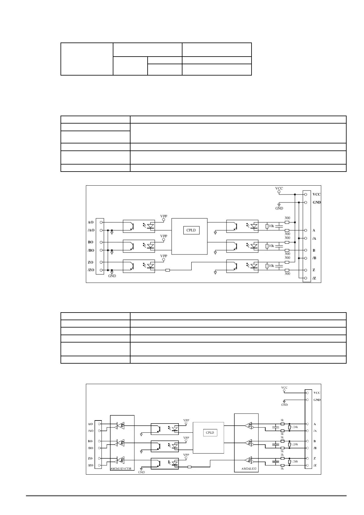
EXP-OC-VDI100 block diagram:
B)
EXP-LD-VDI100 speed feedback card: Line driver speed feedback card
EXP-LD-VDI100terminalspecication
Terminal Name Description
Vcc Power supply for encoder: 12V/5V±5%, 200mA
GND (0V Common Terminal) Power Source and Input Signal Common
A, /A, B, /B, Z, /Z PG Signal Input Terminal (Open Collector Type)
AO, /AO, BO, /BO, ZO, /ZO Pulse monitor output*: Open Collector Type, 24V, 30mA
/AO,/BO,/ZO: Output Signal Common
E Grounding Terminal.
**Use20-29tosetPGpulseoutputratioforA/B-phase(AO/BO),theterminal“ZO”canbeusedtomonitorZ-phasePGpulse.
EXP-LD-VDI100 block diagram:
VDI100 • Instruction manual 345
 Loading...


