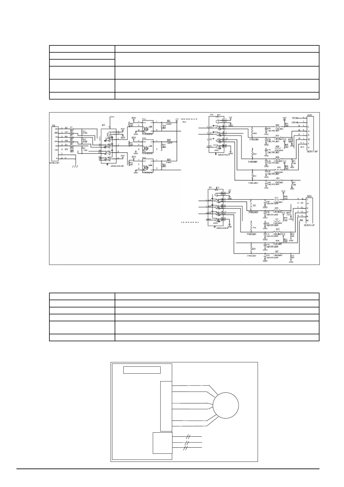
C)EXP-LD-PM-VDI100 speed feedback card: synchronous motor line driver speed feedback card
EXP-LD-PM-VDI100terminalspecication
Terminal Name Description
Vcc Power supply for encoder.
5V ±5%, 200mA Maximum
GND (0V Common Terminal)
A, /A, B, /B, Z, /Z
U, /U, V, /V, Z, /Z
Encoder input signal, A correct divider ratio output requires a two-phase input.
Line driver input type, RS-422 level input.
AO, /AO, BO, /BO, ZO, /ZO A ,B phase divider ratio output, z phase output monitor,
Line driver output type, RS-422 level output.
E Grounding Terminal.
EXP-LD-PM-VDI100 block diagram:
D) EXP-RS-PM-VDI100 speed feedback card with TAMAGAWA Resolver Encoder
EXP-RS-PM-VDI100terminalspecication
Terminal Name Description
R1,R2 Sinusoidal excitation signal. 7Vrms, 10KHz. Transformation ratio: 0.5±5%
S1, S3 Analog input of Sine signal.
S2, S4 Analog input of Cosine signal.
AO, /AO,BO, /BO, ZO, /ZO A and B phase output terminal; Z phase monitoring output terminal.
Line Driver output type: RS-422 Level output
E Grounding terminal
*Thiscardisnotapplicableonsize1models(VDI100-1007…1015-KBX-2T,VDI100-1007…1022-KBX-.-4).
EXP-RS-PM-VDI100 block diagram:
R2
S1
S3
S2
S4
b+, b-,
z+, z-
EXP-RS-PM-VDI100
346 VDI100 • Instruction manual
 Loading...


