9.2. ConnectTransducerFeedbackSignal(10-01)
The PID function in the inverter
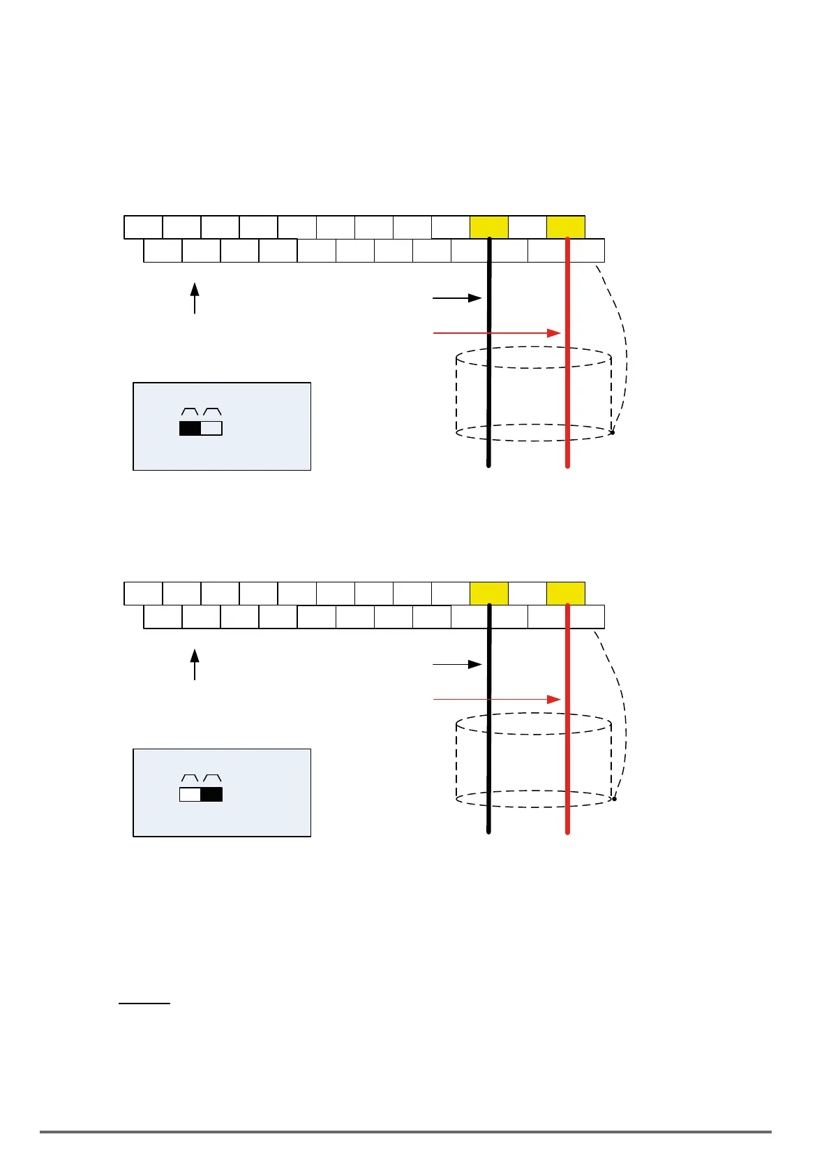
Depending on the type of feedback transducer used, the inverter can be setup for either 0-10V or a 4-20mA
feedback transducer.
FeedbackSignalfromAI2(10-01=2),andsettheinputcurrentto4–20mA/SW2=I
E
DO2
24VG
S2 S4 S6 S8 24V +12V
GND
AI1
AI2
DO1 DOG S1 S3 S5 S7 F1 F2 PI AO1 AO2
E
Connect shield to
control ground
terminal
4 – 20mA
+
-
Analog Input AI2
Common, GND
Control Terminals /
User Terminals
SW2
I V
Set switch SW2 to ‘I’
FeedbackSignalfromAI1(10-01=1),andsettheinputvoltageto0–10V/SW2=V
E
DO2
24VG
S2 S4 S6 S8 24V +12V
GND
AI1
AI2
DO1 DOG S1 S3 S5 S7 F1 F2 PI AO1 AO2
E
Connect shield to
control ground terminal
0 – 10Vdc
+
-
Analog Input AI2
Common, GND
Control Terminals /
User Terminals
SW2
I V
Set switch SW2 to ‘V’
9.3. EngineeringUnits(onlyforLCD)
The PID setpoint scaling can be selected with parameter 16-03 and 16-04.
Example: 0 – 200.0 PSI Setpoint, set 16-03 to 12000 (1 decimal, range 0 – 200) and 16-04 to 2 (PSI).
9.4. Sleep/WakeupFunction
The PID Sleep function can be used to prevent a system from running at low speeds and is frequently used in
pumping application. The PID Sleep function is turned on by parameter 10-29 set to 1. The inverter output turns
328 VDI100 • Instruction manual
 Loading...


