4.1.2. Seven Segment Display Description
Actual LED Display Actual LED Display Actual LED Display Actual LED Display
0
0
A
a
L
l
Y
y
1
1
B
n -
-
2
2
C
c
o
o
°
3
3
D P
p
_
4
4
E
e
q .
.
5
5
F
f
r
6
6
G S
s
7
7
H
h
t
8
8
I
i
u
9
9
J
j
V
u
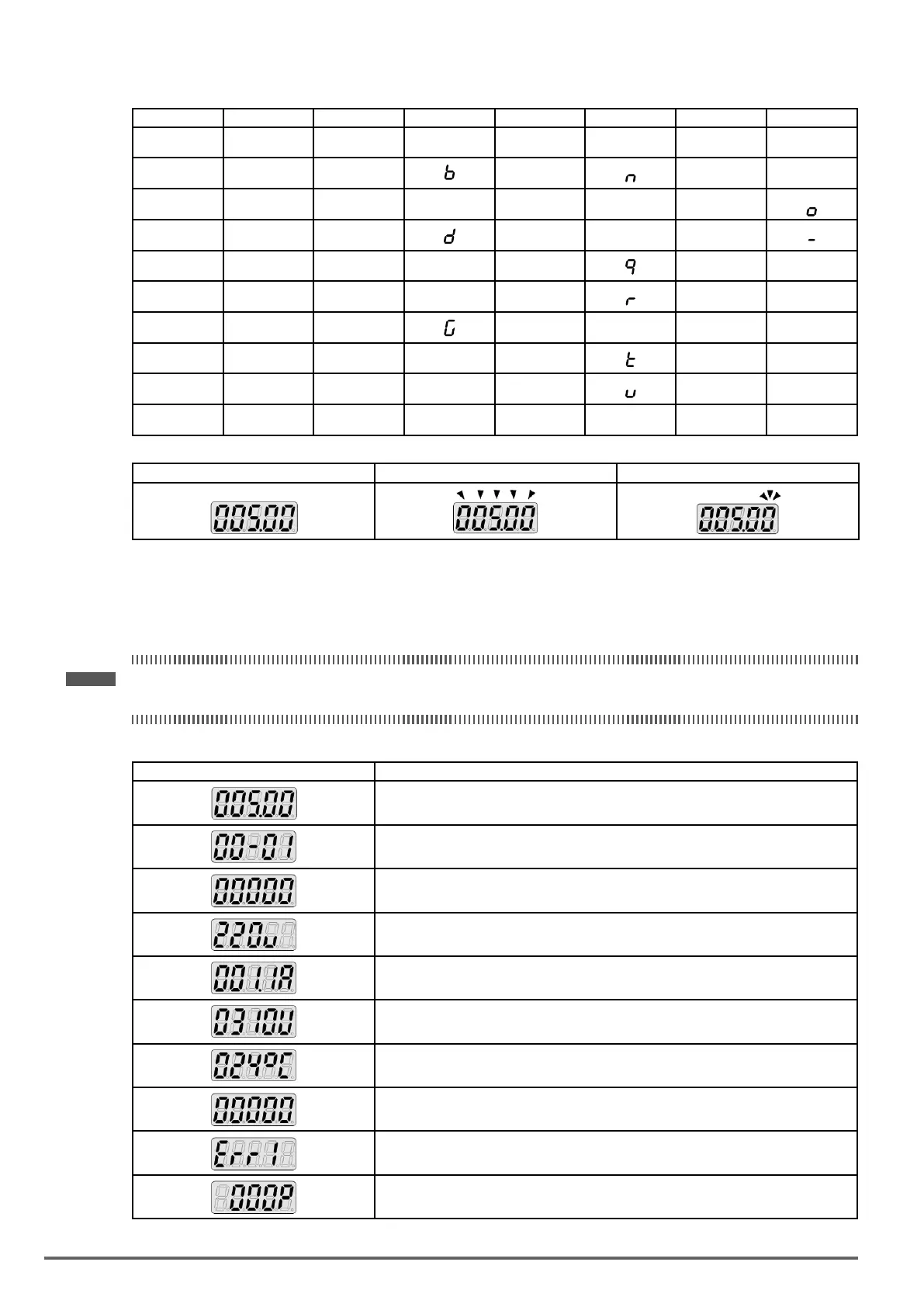
Display output frequency Frequency Reference Set Frequency Reference
LED lights on LED flashes Flashing digit
At power-up, the display will show the frequency reference setting and all LEDs are ashing. Press the ▲ (UP)
or ▼ (DOWN) key to enter the frequency reference edit mode, use the ◄/RESET key to select which digit to
edit (ashing). Use the ▲ (UP) or ▼ (DOWN) key to modify the value and press the READ / ENTER key to
save the frequency reference and switch back to the frequency reference display mode.
• During run operation, the display will show the output frequency.
Note ! When in edit mode and the READ / ENTER is not pressed within 5 sec, the inverter will switch back to the frequency reference
display mode.
LED Display Examples
Seven Segment Display Description
1. Displays the frequency reference at power-up.
2. Displays the actual output frequency during run operation.
Displays parameter code.
Displays the setting value of parameter.
Displays input voltage.
Displays inverter current.
Displays DC Bus Voltage.
Displays temperature.
Displays PID feedback value; The displayed digit is set by 12-01.
Error display; refer to chapter 5 Troubleshooting and Maintenance.
Displays AI1/ AI2 input (0~100%)
46 VDI100 • Instruction manual
 Loading...


