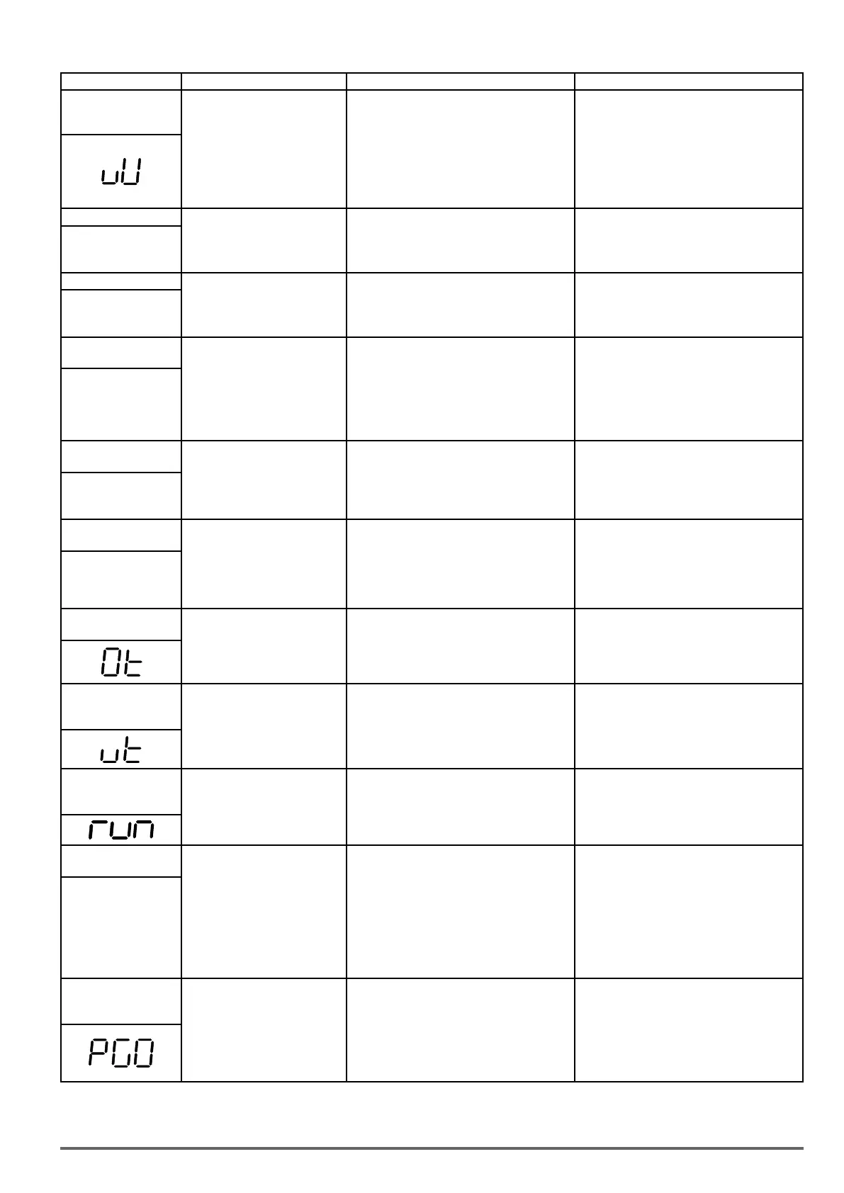
LED display Description Cause Possible solutions
UV
Under voltage
DC bus voltage is lower than
the UV detection level or the
pre-charge contactor is not active
while the inverter is running.
190Vdc: 230V class;
380Vdc: 460V
class
(The detection value can be
adjusted by 07-13).
• The input voltage is too low.
• Input phase loss.
• Acceleration time set too short.
• Input voltage fluctuation.
• Pre-charge contactor damaged.
• DC bus voltage feedback signal value not
incorrect.
• Check the input voltage.
• Check input wiring.
• Increase acceleration time.
• Check power source
• Replace pre-charge contactor
• Replace control board or complete inverter.
IPL input phase loss
Phase loss at the input side of
the inverter or input voltage
imbalance, active when 08-09 =
1 (enabled)
• Wiring loose in inverter input terminal.
• Momentary power loss.
• Input voltage imbalance.
• Check input wiring / faster screws.
• Check power supply
IPL
OPL output phase loss
Phase loss at the output side of
the inverter, active when 08-10 =
1 (enabled).
• Wiring loose in inverter output terminal.
• Motor rated current is less than 10% of the
inverter rated current.
• Check output wiring / faster screws.
• Check motor & inverter rating.
OPL
OH1
Heatsink overheat
The temperature of the heat sink
is too high.
Note: when OH1 fault occurs
three times within five minutes,
it is required to wait 10 minutes
before resetting the fault.
•Ambient temperature too high.
• cooling fan failed
• Carrier frequency set too high.
• Load too heavy.
•Install fan or AC to cool surroundings.
•Replace cooling fan.
•Reduce carrier frequency.
•Reduce load / Measure output current
OHI
OL1
Motor overload
Internal motor overload protection
tripped, active when protection
curve 08-05 = xxx1.
•Voltage setting V/f mode too high, resulting in
over-excitation of the motor.
•Motor rated current (02-01) set incorrectly.
•Load too heavy.
•Check V/f curve.
•Check motor rated current
•Check and reduce motor load, check and
operation duty cycle.
OLI
OL2
Inverter overload
Inverter thermal overload pro-
tection tripped.
If an inverter overload occurs 4 ti-
mes in five minutes, it is required
to wait 4 minutes before resetting
the fault.
• Voltage setting V/f mode too high, resulting
in over-excitation of the motor.
• Inverter rating too small.
• Load too heavy.
•Check V/f curve.
•Replace inverter with larger rating.
•Check and reduce motor load, check and
operation duty cycle.
OL2
OT
Over torque detection
Inverter output torque is higher
than 08-15 (over torque detection
level) for the time specified in
08-16. Parameter 08-14 = 0 to
activate.
• Load too heavy.
• Check over torque detection parameters (08-
15 / 08-16).
• Check and reduce motor load, check and
operation duty cycle.
UT
Under torque
detection
Inverter output torque is lower
than 08-19 (under torque detec-
tion level) for the time specified
in 08-20. Parameter 08-18 = 0 to
activate.
•Sudden drop in load.
•Belt break.
•Check under torque detection parameters
(08-19 / 08-20).
•Check load / application.
run
Switch for Motor1/
Motor2
Switch for Motor1/Motor2 in
running time
• Execute command for switching motor2 in
running time
• Execute command for switching motor in
running time
•Revise the sequence control and switch motor
in top time.
OS
Over speed
Motor speed exceeds level set
in 20-20 (PG Over speed Level)
for the time set in 20-21 (PG over
speed time). Active when 20-19
(= 0 or 1).
This fault is active V/f + PG and
SV control mode (00-00 = 1
or 3 or 4). Motor speed can be
monitored by 12-22
•Motor speed overshoot (ASR)
•PG ppr set incorrectly.
•Overspeed parameters set incorrectly.
•Check ASR parameters group 21.
•Check PG parameters
•Check overspeed parameters 20-20/20-12
O5
PGO
PG
Open circuit
PG pulses are not received by the
inverter for the time specified in
20-26 (PG open circuit detection
time).
This fault is active V/f + PG and
SV control mode (00-00 = 1 or
3 or 4).
•PG cable disconnected.
•PG has no power.
•Mechanical brake active preventing motor
from turning.
•Check PG wiring.
•Check PG power-supply.
•Make sure brake is released.
VDI100 • Instruction manual 331
 Loading...


