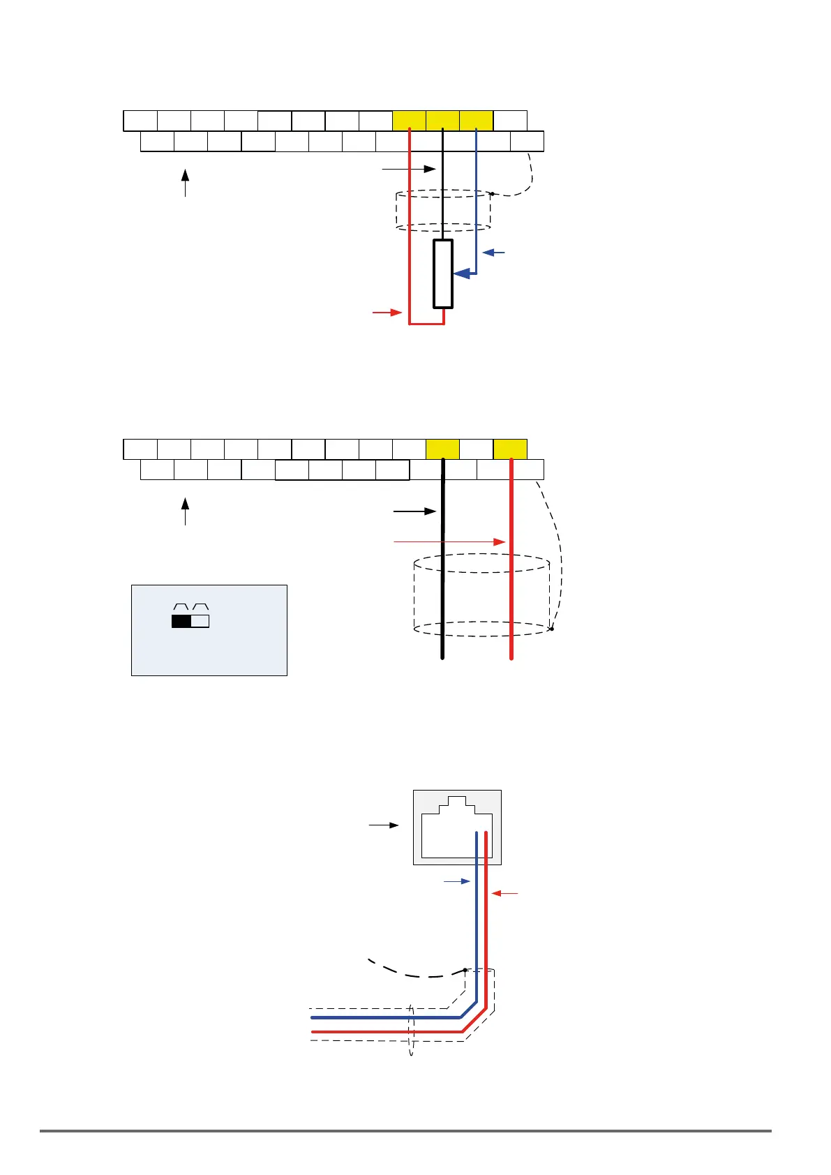
AnalogReference:Potentiometer/SpeedPot(Setting00-05=1)
E
DO2
24VG
S2 S4 S6 S8 24V +12V GND AI1 AI2
DO1 DOG S1 S3 S5 S7 F1 F2 PI AO1 AO2
E
Control Terminals /
User Terminals
Connect shield to
control ground terminal
Potentiometer
1 ~ 5K Ohm
+12VDC, +12V
Common/0V, GND
Analog
Input AI1
AnalogReference:4–20mA(Setting00-05=1)
E
DO2
24VG
S2 S4 S6 S8 24V +12V
GND
AI1
AI2
DO1 DOG S1 S3 S5 S7 F1 F2 PI AO1 AO2
E
Connect shield to
control ground terminal
4 – 20mA
+
-
Analog Input AI2
Common, GND
Control Terminals /
User Terminals
SW2
I V
Set switch SW2 to ‘I’
(Factory Default)
6.3. ReferencefromSerialCommunicationRS485(00-05=3)
RS485 PLC / Computer Connection
-
+
S-
S+
Cable
Shield
RS485 Port
CN6
Control board
To set the speed reference for the inverter via serial communication parameter 00-05 has be set to “3” for fre-
quency command via serial communication.
312 VDI100 • Instruction manual
 Loading...


