Acceleration and deceleration times are represented by the three most signicant (high order) digits. Set accel-
eration and deceleration times with respect to maximum frequency. The relationship between the set frequency
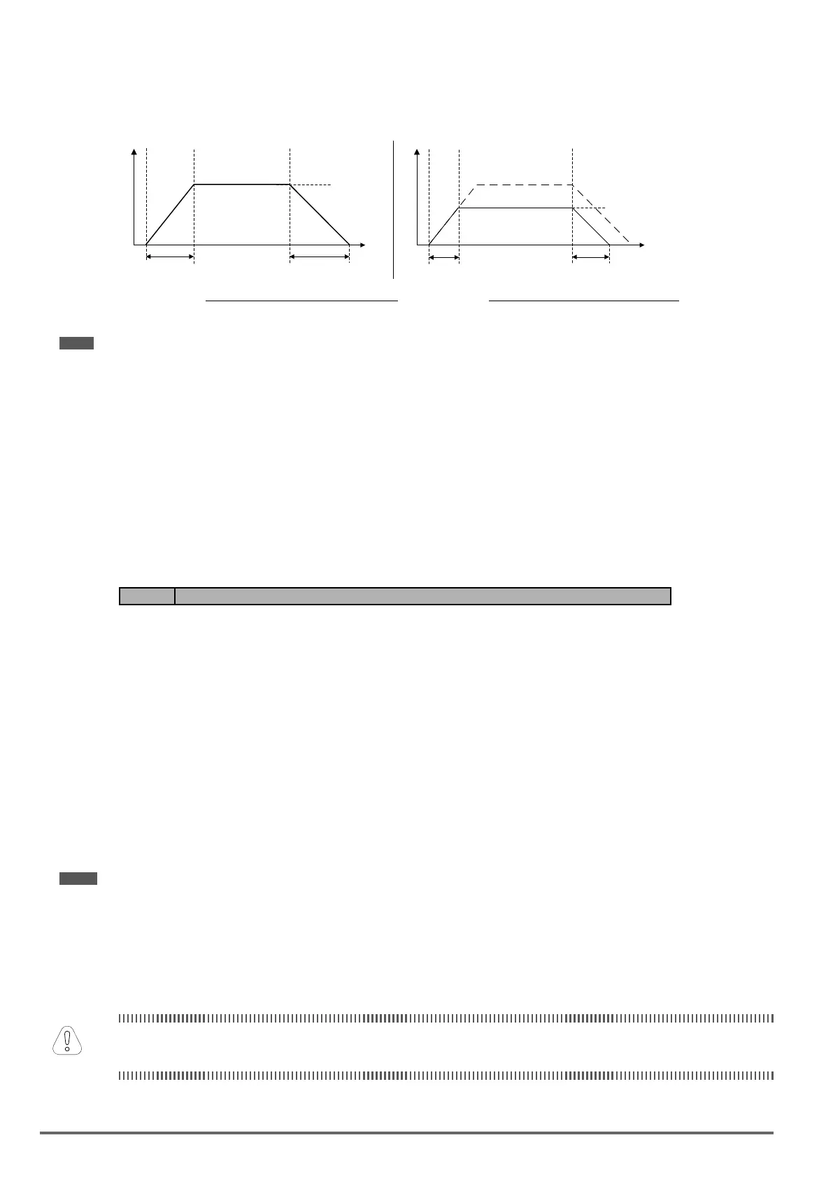
value and acceleration/deceleration times is as follows:
Output frequency
Acceleration time
Set frequency
Time
Deceleration time
Maximum frequency
Acceleration time
Set frequency
Time
Deceleration time
Maximum frequency
RUN STOPRUN STOP
SetFrequency=MaximumFrequency SetFrequency<MaximumFrequency
Note: If the set acceleration and deceleration times are set too low, the torque limiting function or stall prevention function can become
activated if the load torque and or inertia are relatively high. This will prolong the acceleration and or deceleration times and not
allow the set times to be followed. In this case the acceleration and or the deceleration times should be adjusted.
8.3. TorqueCompensationGain(01-10)
This parameter sets the relationship between output frequency and output voltage. Constant torque applica-
tions have the same torque requirements at low speed as well as at high speed.
Initial Setup
For Variable Torque / Normal Duty applications set parameter 01-10 to an initial value of 0.5.
For Constant Torque / Heavy Duty applications set parameter 01-10 to an initial value of 1.0.
Code Parameter Name / Range
01-10 Torque compensation gain
This parameter sets the torque boost for motor 1.
Setting range: 0.0 to 2.0
To set parameter 01-10:
- After power-up press the DSP/FUN key
- Set Group 01 (V/f Pattern), and select parameter -10 with the UP/DOWN ▲ and ▼ keys and press the
READ/ENTERkey.
Increase value when:
• The wiring between the inverter and the motor very too long
• The motor size is smaller than the inverter size
Note: Gradually increase the torque compensation value and make sure the output current does not exceed inverter rated current.
Reduce value when:
• Experiencing motor vibration
• Over Current Fault
• Overload Fault
Conrm that the output current at low speed does not exceed the rated output current of the inverter.
Vérierquelecourantdesortieàbassevitessenedépassepaslavaleurnominaledel’inverseur.
320 VDI100 • Instruction manual
 Loading...


