Chapter 7. How to Use Speed Servo
7-11
7.8 Using Monitor
The servo's internal speed command and torque, and the feedback motor speed can be
monitored from outside through the analog output (MONIT1) and (MONIT2). The range of
output voltage is -4[V] - 4[V]. The following are the parameters related to the use of the motor.
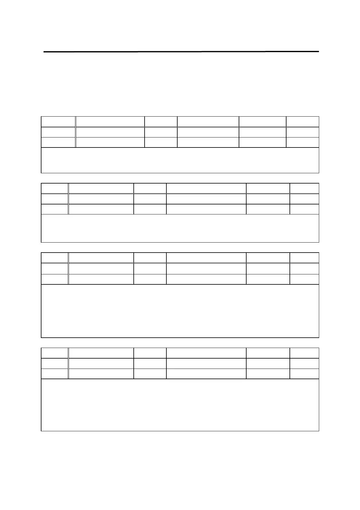
Menu Menu name Unit Display range Initial value Mode
P2-11 Monitor1 Select 0 ~ 2 0 SPT
P2-15 Monitor2 Select 0 ~ 2 1 SPT
Sets parameters to be output on the monitor.
(0: speed, 1: torque, 2: speed command)
Menu Menu name Unit Display range Initial value Mode
P2-12 Monitor1 ABS 0, 1 0 SPT
P2-16 Monitor2 ABS 0, 1 0 SPT
0: Outputs codes by type.
1: Outputs absolute values without classifying codes.
Menu Menu name Unit Display range Initial value Mode
P2-13 Monitor1 Scale Multiple 1.00 ~ 20.00 1.00 SPT
P2-17 Monitor2 Scale Multiple 1.00 ~ 20.00 1.00 SPT
This is used to allow viewing by multiplying parameters by appropriate scale in case the
analog output values are too small to monitor. For example, if 3 is input, the size of the
parameter is magnified by 3 times.
Basic scale: Speed, and speed command (Maximum speed/4[V])
Torque (3 x rated torque)/4[V]
Menu Menu name Unit Display range Initial value Mode
P2-14 Monitor1 offset % -100.0 ~ 100.0 0.0 SPT
P2-18 Monitor2 offset % -100.0 ~ 100.0 0.0 SPT
This is used to output values by applying appropriate offset to the analog output values. This
is to enable adjustment of the values output on 0[V] potential by applying offset to the
monitor output. Unit used is [%], and the maximum value is 100 [%]. If the speed is output
assuming the maximum speed as being 5000[RPM], 1000[RPM], 20[%] of 5,000, is
displayed on 0[V] when offset 20 is loaded.