Chapter 9. How to Use Torque Servo
9-3
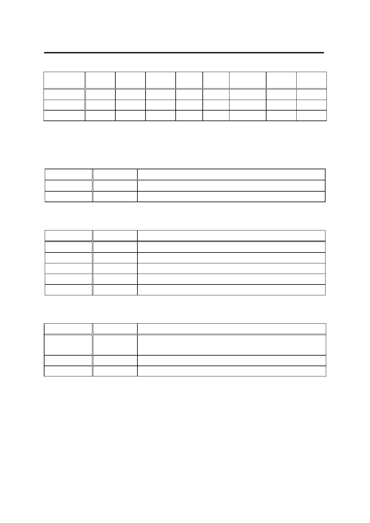
Alarm
type
Emerg.
Stop
Over-
current
Over-
voltage
Over-
load
Power
error
Encoder
miswiring
Others Normal
A_CODE0 ON OFF ON OFF ON OFF ON OFF
A_CODE1 ON ON OFF OFF ON ON OFF OFF
A_CODE2 ON ON ON ON OFF OFF OFF OFF
Where ON: Applicable contact is connected to "GND24".
OFF: Applicable contact is connected to "+24V", or applicable contact not connected.
9.2.3 Analog input use and function table
Name Pin No. Function and Use
SPDIN 27 Inputs external analog speed limit (-10V ~ +10V).
TRQIN 28 Inputs external torque command (-10V ~ +10V).
9.2.4 Analog output use and function table
Name Pin No. Function and Use
MONIT1 3 Monitor output 1 (-4V ~ +4V)
MONIT2 2 Monitor output 2 (-4V ~ +4V)
PAO, /PAO 7, 32 A phase, /A phase encoder signal output
PBO, /PBO 6, 31 B phase, /B phase encoder signal output
PZO, /PZO 5,30 Z phase, /Z phase encoder signal output
9.2.5 I/O contact power supply
Name Pin No. Function and Use
GND
1, 8, 26
33, 34, 36
Power ground for analog I/O, such as speed command,
torque limit command, monitor output and encoder output.
+24VIN 49 DC 24V power supply for the external I/O contact
GND24 24, 25 DC 24V ground for the external I/O contact
(Note) See section 3.4.6 for the capacity of +24V power supply.
9.3 CN2 Wiring
For information on CN2 wiring, see "Section 3.5 CN2 Wiring and Signal Description".
 Loading...