Chapter 3. Wiring and Signals
3-3
3.3 Main Circuit Terminal Board Wiring
3.3.1 Main circuit terminal board wiring
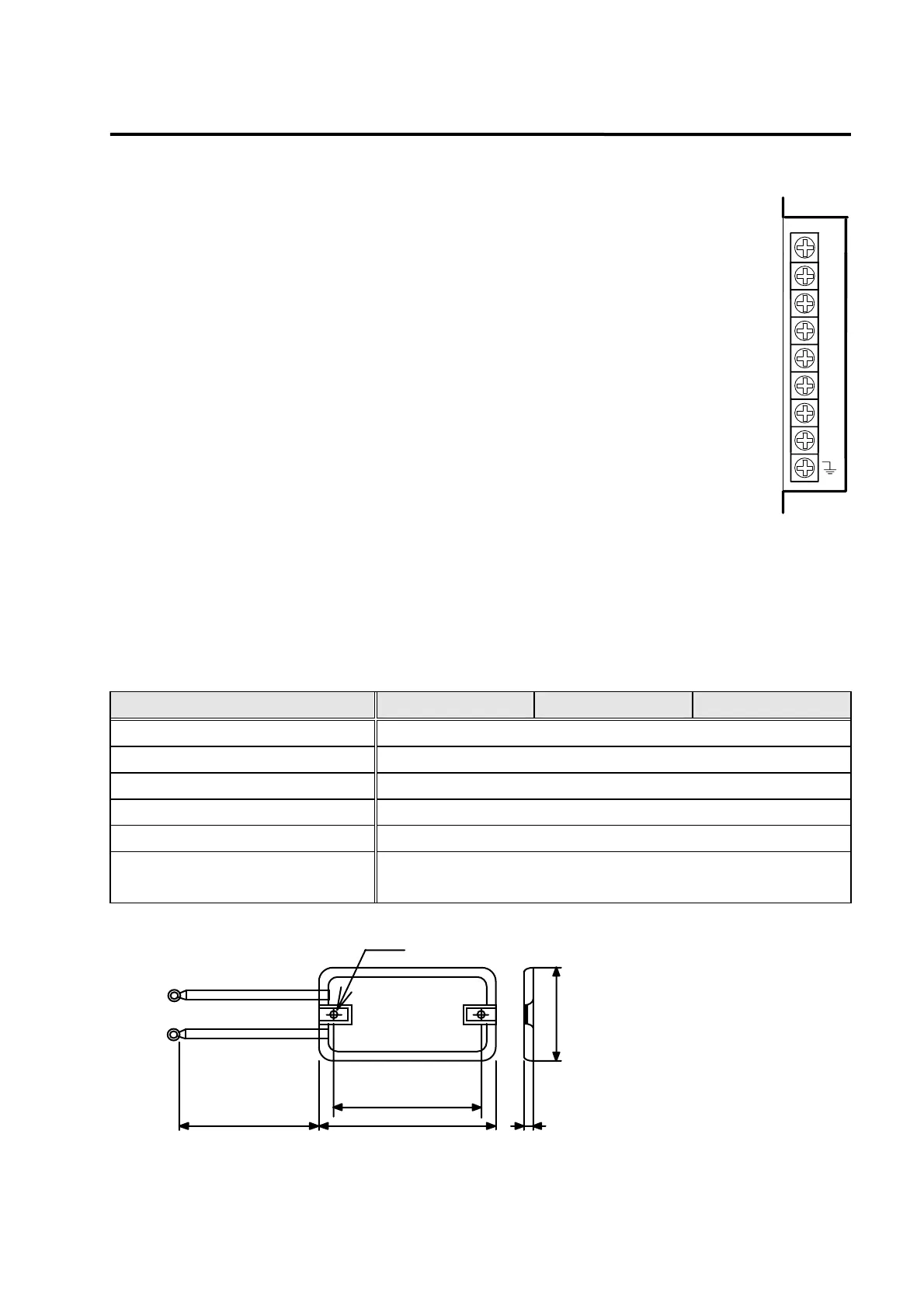
Open the main circuit terminal board cover to see the terminal board. Terminal names
are located on the right side of the terminal board. (See figure on the right side.)
Uses and wiring methods of FDA-5001-5004 are as follows.
1) The R, S and T terminals are used to connect main power supply of 3-phase AC
200-230 [V] to the power circuits.
*
(Note) Single-phase AC 220V may also be used; however, output may be lower
than the rated value.
Install overcurrent breaker on the main power supply input unit. Also, install noise
filter on the power supply input terminal to shut off noise coming from the power
lines.
2) Connect regenerated resistance between P and B terminals. The standard regenerated
resistance (See Table 3.1) is a standard item. (Install it on the electric panel.)
3) Connect the U, V and W phases of the servo motor to the U, V and W terminals.
4) Ground the terminal. Also connect the servo motor earth cable to this terminal.
[Table 3.1. Recommended parts to be installed on electric panel]
AC Servo drive system FDA-5001 FDA-5002 FDA-5004
Wire thickness AWG #16 ( 1.25 mm
2
)
Drive system side press terminal KET GP110012
Switch GMC-12 ( 13A ) or equivalent
Breaker ABS 33b ( 5A ) or equivalent
Noise filter NFS 305 or NFS 310
Standard regenerated resistance
(for P and B terminals)
50W 50Ω
( Size: Refer to external view1 )
[External view1 ] 50W 50Ω
500±20
78±0.5
90±1
43±1
6
4.3
S
T
U
V
W
R
P
B
 Loading...