Chapter 3. Wiring and Signals
3-1
3. Wiring and Signals
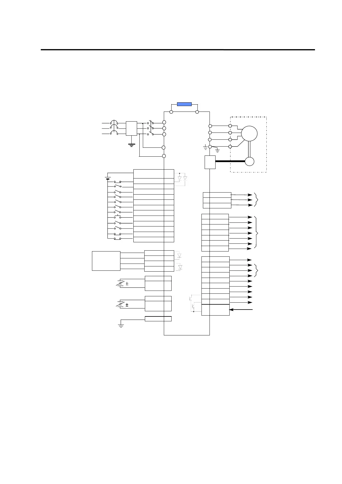
3.1 Representative wiring
+24VIN
ESTOP
SPD1 / GEAR1
SPD2 / GEAR2
DIR
SVONEN
ALMRST/CLR
TLIM
PI/P
CWLIM
CCWLIM
/PAO
PAO
/PBO
PBO
30
5
/PZO
PZO
A_CODE0
A_CODE1
A_CODE2
INSPD/INPOS
RDY
ZSPD
BRAKE
ALARM
GND24
Emergency stop
Speed/Electric gear
select
Motor stop/start
Servo enable
Alarm reset/Cumulative pulse clear
Analog torque limit
PI/P select
CCW limit
CW limit
Line driver
pulse frequency
division output
(Frequency division set
1/1,1/2,1/3,...,1/16)
In speed
/In position
Servo ready
Zero speed
Torque under limit
Torque mode operating
Brake output
Alarm status
+24V GND
24V
PFIN
PPRIN
PRIN
10
9
12
SPDIN
TRQIN
27
28
GND
GND
1
34
36
FG 50
Analog speed command
/Analog speed limit
Analog torque command
/analog torque limit
F.G
MONIT1
MONIT2
Monitor output
(0 ~ 5V)
MCCB1
MC1
Regenerative resistor
(seperately installed)
GND
15
40
41
14
38
18
13
16
17
43
39
7
32
31
6
45
19
44
22
21
47
48
20
24
25
CN1
3
2
CN1
T
S
R
8
PPFIN 11
(Note3)
(Note1)
U
V
W
E
Servo
motor
Encoder
U
V
W
CN2
Position
command pulse
P
B
Power Supply
AC 200 ~ 230 V
50/60 Hz
49
SPD3 / TYPE
42
33
TRQOUT
46
FDA-5000
Direction of rotation select
10V
ALARM CODE
(Input)
(Output)
5[V]Line Drive,
Open Collector
Speed/Control type select
NF
10V
8
GND
r
t
(Note2)
y Note 1: NF is an abbreviation for Noise Filter. Use this to prevent infiltration of noise from
external sources.
y Note 2: For FDA-5005-75 type, connect single-phase AC220 [V] to the r and t terminals of the
spare power supply.
FDA-5001-4 type is not provided with r and t terminals.
y Note 3: Use CN1 earth cable to ground the F.G. (Frame Ground) terminals.
-4 ~ +4V
 Loading...