LUBRICATION SYSTEM
5-7
OIL PRESSURE RELIEF VALVE
REMOVAL
Separate the crankcase (page 14-5).
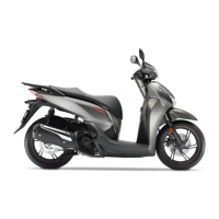
Remove the oil pressure relief valve and O-ring
from the left crankcase.
INSPECTION
• Be careful not to loose the disassemble parts.
Check the operation of the oil pressure relief valve
by pushing on the piston.
Remove the snap ring, washer, spring and piston
from the oil pressure relief valve body.
Check the piston for wear, sticking or damage.
Check the valve spring for wear or damage.
Check the relief valve body for clogging or damage.
Clean all parts and assemble the relief valve in the
reverse order of disassembly.
• Install the snap ring with the chamfered edge
facing the thrust load side.
• Do not reuse worn snap ring which could easily
spin in the groove.
• Check that the snap ring is seated in the groove.
INSTALLATION
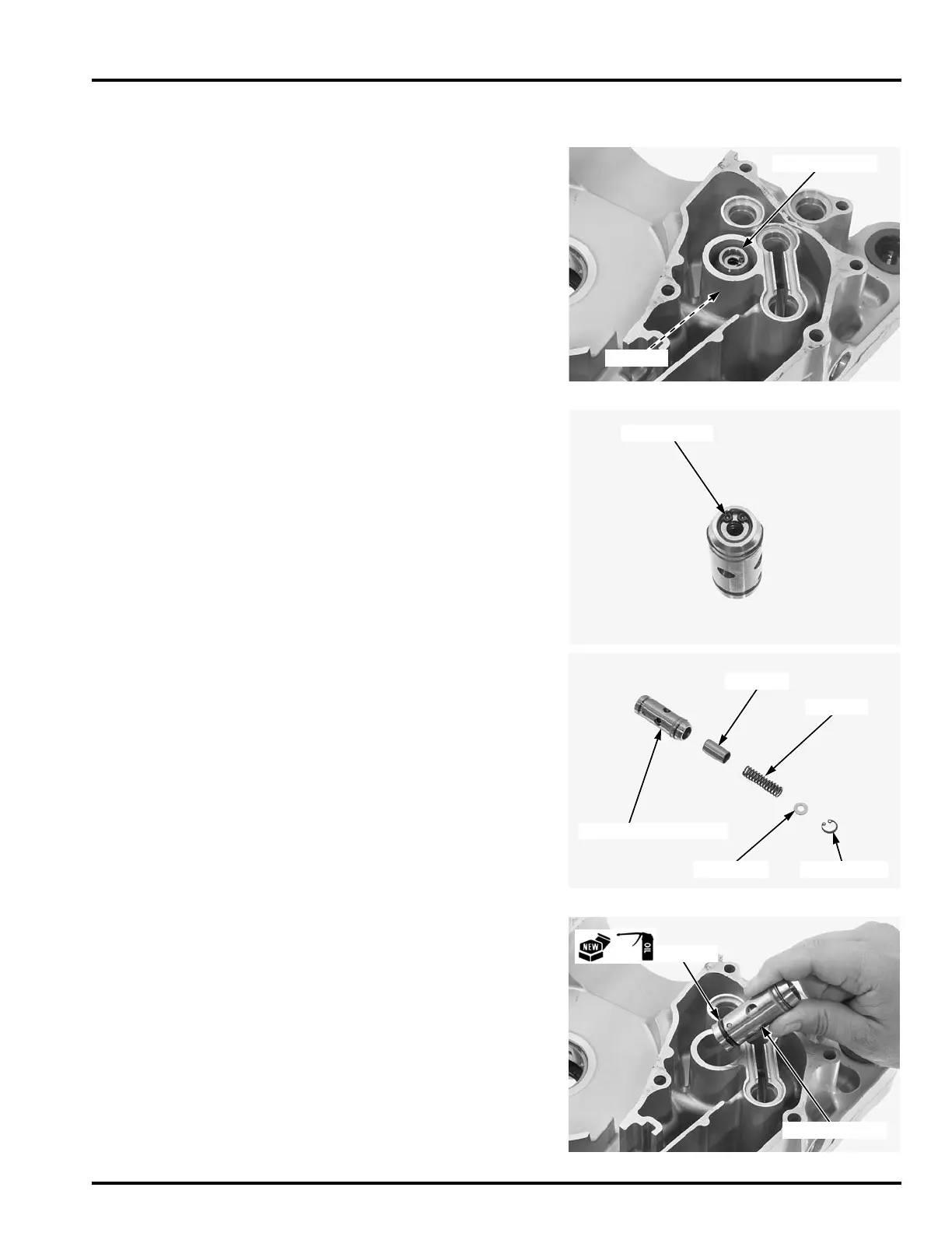
Coat a new O-ring with engine oil and install it to
the oil pressure relief valve.
Install the oil pressure relief valve into the left crank-
case.
Assemble the crankcase (page 14-14).
The snap ring is
under spring pres-
sure. Use care
when removing it
and wear eye and
face protection.
PISTON
WASHER
SPRING
SNAP RING
RELIEF VALVE BODY
 Loading...