FRAME/BODY PANELS/EXHAUST SYSTEM
3-13
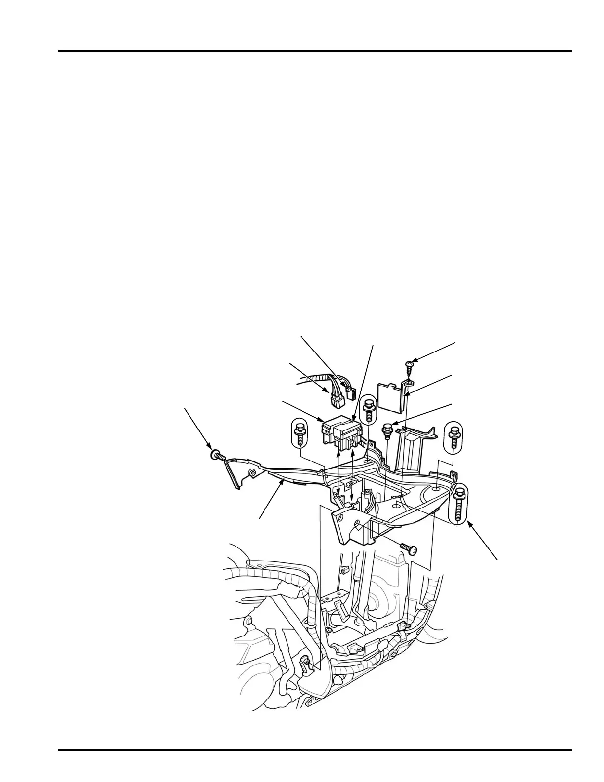
FLOOR PANEL
Remove the following:
– body cover (page 3-6)
– floor side cover (page 3-8)
– front inner cover (page 3-10)
– battery (page 19-6)
– starter relay (page 21-15)
Release the following:
– fuse box A
– DLC
– fuse box B (ABS type only)
– ABS service check connector (ABS type only)
Remove the two screws, four washer bolts and spe-
cial bolt.
Remove the tapping screw and wire holder.
Pull out the electric cables, wire harness, fuse box A,
fuse box B (ABS type only), DLC and ABS service
check connector (ABS type only) through the hole of
the floor panel.
Remove the floor panel.
Installation is in the reverse order of removal.
Route the cables
properly
(page 1-19).
FLOOR PANEL
FUSE BOX A
TAPPING SCREW
HOLDER
SCREWS
SPECIAL BOLT
WASHER BOLTS
ABS SERVICE CHECK
CONNECTOR (ABS type only)
FUSE BOX B
(ABS type only)
DLC
 Loading...