LIGHTS/METERS/SWITCHES
22-24
REMOVAL/INSTALLATION
STD type: Remove the front upper cover (page 3-9).
Remove the front Lower cover (page 3-12).
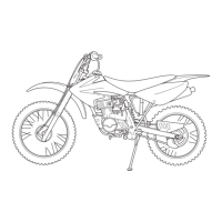
Remove the fan motor relay from the relay connec-
tor.
Installation is in the reverse order of removal.
MAIN RELAY
INSPECTION
All lighting system does not operate
Turn the ignition switch OFF.
Remove the main relay (page 22-26).
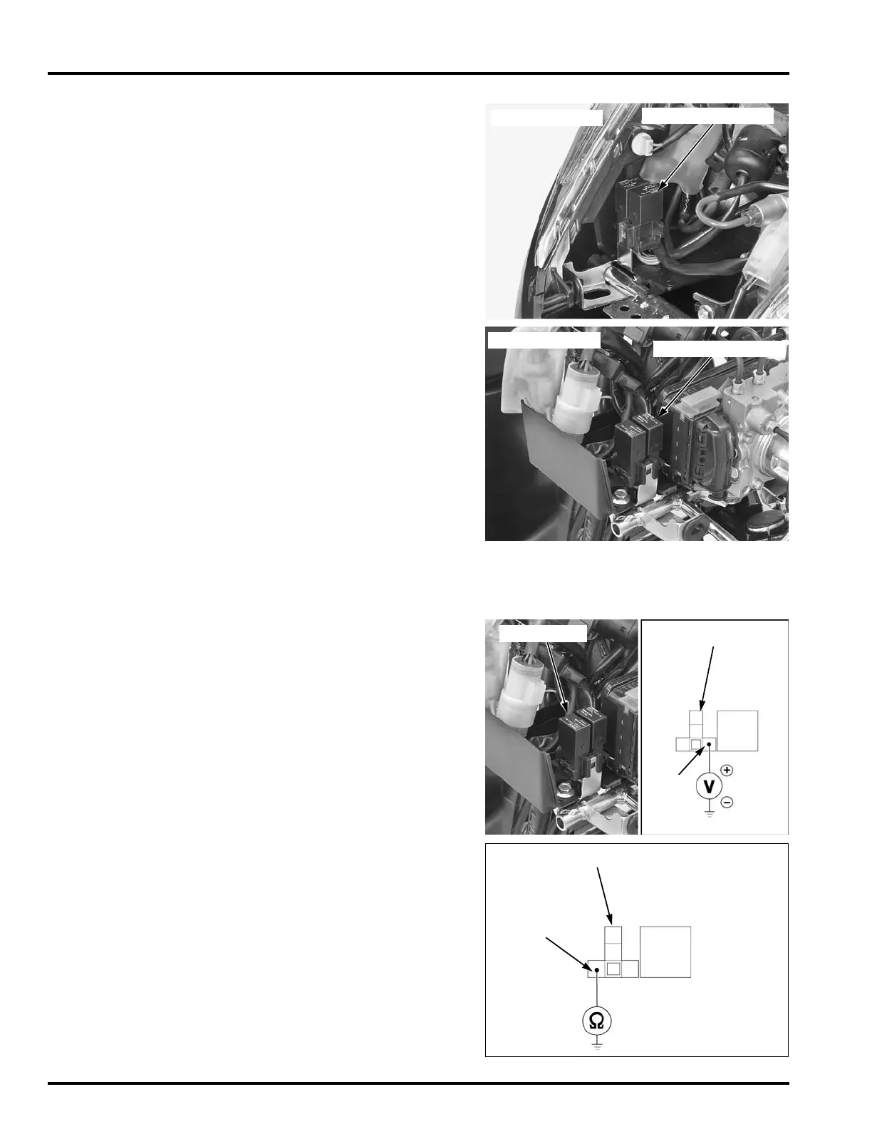
Measure the voltage between the relay connector
terminal of the wire harness side and ground.
If the battery voltage does not appear, inspect the
open circuit in Red/Black wire between the ignition
switch and main relay coil line side.
If the battery voltage appears, the main relay coil
input voltage line is normal.
Inspect the following:
Turn the ignition switch OFF.
Check for continuity between the relay connector
and ground.
There should be continuity at all times.
If there is no continuity, check for open circuit in
Green wire.
If the Green wire is normal, check the following:
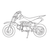
ABS type:
FAN MOTOR RELAY
STD type shown:
ABS type shown:
FAN MOTOR RELAY
Connection: Red/Black (+) – Ground (–)
RELAY CONNECTOR
MAIN RELAY
R/Bl
Connection: Green – Ground
 Loading...