LIGHTS/METERS/SWITCHES
22-23
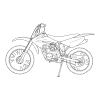
Turn the ignition switch OFF.
Short the relay connector terminals of the wire har-
ness side with a jumper wire.
Remove the front inner cover (page 3-10).
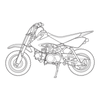
Disconnect the fan motor 2P (Black) connector.
Turn the ignition switch "ON".
Measure the voltage between the fan motor 2P
(Black) connector of the wire harness side and
ground.
If the battery voltage appears, the fan motor relay
switch line is normal.
Inspect the fan motor relay function test (page 22-
23).
If the battery voltage does not appear, inspect the
following:
– Open circuit in Blue wire between the fuse box
and fan motor relay switch line side
– Open circuit in Black wire between the fan motor
relay and fan motor
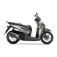
FUNCTION TEST
Remove the fan motor relay (page 22-24).
Connect an ohmmeter to the switching side relay
terminals.
Connect a 12 V battery to the coil side relay termi-
nals.
There should be continuity while the battery is con-
nected to the relay terminals and there should be no
continuity when the battery is disconnected.
Connection: Black – Blue
Connection: Black (+) – Ground (–)
RELAY CONNECTOR
JUMPER WIRE
FAN MOTOR 2P
(BLACK)
CONNECTOR
2P CONNECTOR
(Wire side of female
terminals)
Bl
Bu
Bl
CONNECTION: A – B
CONNECTION: C (+) – D (–)
 Loading...