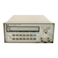
HP
5384A and
HP
5385A
Service
manual. If
the
manual change sheets are
m1ssrng,
contad
your
local Hewlett-Packard
Sales
and Support
Office.
See
the
listing
on
the
back
cover
of
this
manual.
8-10.
Revision letters (A,
B,
etc.)
denote
changes in
printed
circuit layout. For example, if a capacitor type
is
changed (electrical value may remain the same) and
requires
different
spacing
for
its
leads, the
printed
circuit board layout
is
changed and
the
revision letter
is
incremented
to
the next letter.
When
a revision letter
changes the series
number
is
also usually changed. The
production
code
is
the
four-digit
seven-segment
num-
ber
used
for
production
purposes.
8-11. SAFETY CONSIDERATIONS
8-12.
Although
this
instrument
has been designed
in
accordance
with
international
safety standards, this
manual contains
information,
cautions, and warnings
which
must be
followed
to
ensure safe
operation
and
to
retain the
instrument
in safe
condition.
Service and
adjustments
should
be
performed
only
by service-
trained
personnel.
I WARNING I
ALL
PROTECTIVE
EARTH
TERMINALS,
EX-
TENSION CORDS, AUTOTRANSFORMERS
AND
DEVICES
CONNECTED TO
THE
INSTRU-
MENT
SHOULD
BE
CONNECTED TO A PRO-
TECTIVE
EARTH
GROUNDED SOCKET.
ANY
INTERRUPTION OF
THE
PROTECTIVE
EARTH
GROUNDING
WILL
CAUSE
A
POTENTIAL
SHOCK HAZARD
THAT
COULD
RESULT
IN
PERSONAL
INJURY.
ONLY
THE-250V
FUSES
WITH
THE
REQUIRED
RATED
CURRENT AND
SPECIFIED
TYPE
SHOULD
BE
USED.
DO
NOT
USE
REPAIRED
FUSES
OR
SHORT CIRCUITED
FUSEHOLDERS.
TO
DO
SO COULD
CAUSE
A SHOCK OR
FIRE
HAZARD.
8-13.
Any
adjustments,
maintenance,
and repair
of
the
opened
instrument
under
voltage
should
be
avoided
as
much
as
possible and,
when
inevitable,
should
be carried
out
only
by
a skilled person
who
is
aware
of
the
hazard
involved.
8-14. Capacitors inside
the
instrument
may still
be
charged even if
the
instrument
has
been
discon-
nected
from
its source
of
power.
8-2
WARNING I •
LINE
VOLTAGE
IS
ALWAYS
PRESENT
AT
THE
POWER
CORD
CONNECTOR, AC
LINE
FUSE
AND TRANSFORMER
WHENEVER
THE
LINE
CORD
IS
ATTACHED.
UNPLUGGING
THE
POWER
CORD
IS
NECESSARY
TO
REMOVE
ALL
POWER FROM
THE
INSTRUMENT.
8-15.
Whenever
it
is
likely
that
grounding
or
fuse
protection
has
been
impaired,
the
HP
5384A/HP must
be
made
inoperative
and secured against any
unin-
tended
operation.
WARNING I
THE
SERVICE
INFORMATION
IS
OFTEN
USED
WITH
POWER
SUPPLIED
AND
PROTECTIVE
COVERS. REMOVED FROM
THE
HP 5384A/
HP
5385A.
ENERGY
AVAILABLE
AT
MANY
POINTS MAY,
IF
CONTACTED,
RESULT
IN
PERSONAL
INJURY.
8-16. Safety Symbols
8-17. The
following
safety symbols
shown
in Fig-
ure
8-1
are used
on
equipment
and
in
manuals:
8-18. RECOMMENDED TEST
EQUIPMENT
8-19.
Test
equipment
and test
equipment
acces-
sories
required
to
maintain
the
HP 5384A/HP 5385A
are
listed in Table 1-2.
Equipment
other
than
that
listed may be used
if
it meets the critical specifications.
8-20. SERVICE
AIDS
8-21. Pozidriv Screwdrivers
8-22.
Many
screws in
the
counter
appear
to
be
Phillips,
but
are
not.
To
avoid damage
to
the
screw
slots,
pozidriv
screwdrivers
should
be
used.
8-23.
Nut
Drivers
8-24. The BNC
input
connectors on
the
front
and
rear
panels have ring nuts
to
hold
them
in
place.
To
remove
or
tighten
the
nuts
without
damaging
the
panel, place tape
on
the
end
of
the
nut
driver
to
act
as
a cushion.
•
•

 Loading...