•
•
•
8-166. The 12-character, 14-segment Liquid Crystal
Display
(LCD) contains
built-in
temperature
compen-
sated display drivers. The display shows the results
of
frequency
or
period
calculations made by
the
micro-
computer.
The display
information
is
updated a
maximum
of
four
times
per
second.
8-167. SIGNAL DESCRIPTIONS
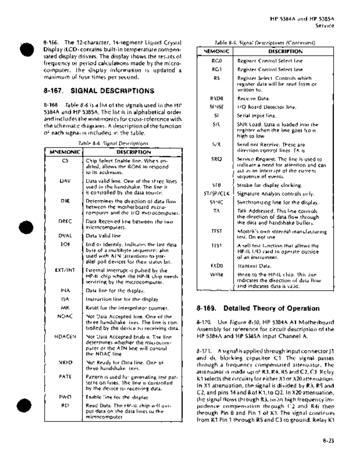
8-168. Table 8-6
is
a list
of
the
signals used in the
HP
5384A and
HP
5385A. The list
is
in alphabetical
order
and includes the mnemonics
for
cross-reference
with
the
schematic diagrams. A description
of
the
function
of
each signal
is
included
in
the
table.
Table 8-6. Signal Descriptions
MNEMONIC
DESCRIPTION
cs
Chip
Select Enable line.
When
en-
abled, allows
the
ROM
to
respond
to
its addresses.
DAY
Data valid line.
One
of
the
three
lines
used in
tbe
handshake. The line
is
is
controll~d
by
the
data source.
DIR
Determines
the
direction
of
data
flow
between
the
motherboard
micro-
computer
and
the
1/0
microcomputer.
DREC
Data Received
line
between
the
two
microcomputers.
DVAL
Data Valid line.
EOI
End
or
Identify.
Indicates
the
last data
byte
of
a
multibyte
sequence; also
used
with
ATN (attention)
to
par-
allel
poll
devices
for
their
status bit.
EXT/INT
External
Interrupt
is
pulsed by
the
HP-IL
chip
when
the
HP-IL
chip
needs
servicing by
the
microcomputer.
INA
Data
line
for
the
display.
ISA
Instruction
line
for
the
display.
MR
Reset
for
the
interpolator
counter.
NDAC
Not
Data Accepted line.
One
of
the
three
handshake lines. The
line
is
con-
trolled
by
the
device
(s)
receiving data.
NDACEN
Not
Data Accepted Enable. The
line
determines
whether
the
microcom-
puter
or
the
ATN
line
will
control
the
NDAC
line.
NRFD
Not
Ready
for
Data line.
One
of
three
handshake lines.
PATT
Pattern
is
used
for
generating test pat-
terns
on
lines. The
line
is
controlled
by
the
device
(s)
receiving data.
PWO
Enable
line
for
the
display.
RD
Read Data. The
HP-IL
chip
will
out-
put
data
on
the
data lines
to
the
microcomputer.
HP
5384A and
HP
5385A
Service
Table 8-6 Signal Descriptions
(Continued)
NEMONIC
DESCRIPTION
RGO
Register
Control
Select line.
RG1
Register
Control
Select line.
RS
Register Select.
Controls
which
register data
will
be read
from
or
written
to.
RXDO
Receive Data.
SENSE
1/0
Board
Detector
line.
Sl
Serial
Input
line.
S/L
Shift Load. Data
is
loaded
into
the
register
when
the
line
goes
from
high
to
low.
S/R
Send
not
Receive. These are
direction
control
lines. TA
is
SRQ
Service Request. The
line
is
used
to
indicate a need
for
attention
and can
act
as
an
interrupt
of
the
current
sequence
of
events.
STB
Strobe
for
display
clocking.
ST/SP/CLK
Signature Analysis
controls
only.
SYNC
Synchronizing
line
for
the
display.
TA
Talk Addressed. This
line
controls
the
direction
of
data
flow
through
the
data and handshake buffers.
TEST
Mostek's
own
internal
manufacturing
test.
Do
not
use.
TEST
A self test
function
that allows
the
HP-IL
1/0
card
to
operate
outside
of
an
instrument.
TXDO
Transmit Data.
Write
Write
to
the
HP-IL chip. This
line
indicates
the
direction
of
data
flow
and indicates data
is
valid.
8-169. Detailed Theory
of
Operation
8-170.
Use
figure
8-50,
HP
5384A
A1
Motherboard
Assembly
for
reference
for
circuit
description
of
the
HP
5384A and
HP
5385A
input
Channel
A.
8-171. A signal
is
applied
through
input
connector
]1
and de
blocking
capacitor
C1.
The signal
passes
through
a
frequency
compensated attenuator. The
attenuator
is
made
up
of
R3,
R4,
RS
and C2,
C3.
Relay
K1
selects the circuitry
for
either
X1
or
X20
attenuation.
In
X1
attenuation,
the
signal
is
divided
by
R3,
RS
and
C2, and pins
14
and 8
of
K1,
to
Q2. In
X20
attenuation,
the signal flows
through
R3,
(with high
frequency
im-
pedence compensation
through
C2 and
R4)
then
through
Pin
8 and
Pin
1
of
K1.
The signal continues
from
K1
Pin
1
through
RS
and
C3
to
ground.
Relay
K1
8-23

 Loading...


