•
•
•
HP
5384A and
HP
5385A
General
Information
SECTION I
GENERAL INFORMATION
1-1. INTRODUCTION
1-2. This manual provides you
with
information
pertaining
to
the
installation,
operating,
program-
ming,
performance
tests, adjustments, and
main-
tenance
of
the
Hewlett-Packard
Models
5384A and
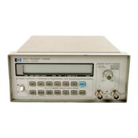
5385A Frequency Counters, shown
in
Figure 1-1. ·
1-3. MANUAL SUMMARY
1-4. The manual
is
divided
into
eight
sections, each
covering a
particular
topic
for
the
operation
of
the
HP
5384A and
HP
5385A Frequency Counters. The topics
by section
number
are:
Section
II
Ill
IV
v
VI
VII
VIII
Topic
General
Information
Installation
Operation
and Programming
Performance
Tests
Adjustments
Replaceable
Parts
Manual
Changes
Service
1-5. SPECIFICATIONS
1-6. The
instrument
specifications and
option
speci-
fications are
listed
in
Table
1-1. These specifications
are
performance
standards
or
limits against
which
the
instrument
may be tested.
1-7. SAFETY CONSIDERATIONS
1-8. This
is
a Safety
Class
I instrument. This
instru-
ment
has
been designed and tested according
to
international
safety requirements.
1-9. This
manual contains
information,
cautions,
and warnings
which
must be
followed
by
operating
and service personnel
to
ensure safe
operation
and
to
retain
the
instrument
in safe
condition.
1-10. DESCRIPTION
1-11. The Hewlett-Packard
Models
5384A and 5385A
are
frequency
counters that make
frequency
and
period
measurements. The
HP
5384A has a
frequency
range
of
10
Hz
to
225
MHz,
and
the
HP
5385A
has
a
frequency
range
of
10Hz
to
1000
MHz.
Both counters
are
microcomputer
based instruments
with
a data bus
port
for
remote
operation
through
either
HP-IL
or
HP-IB.
1-12. Both counters have
"A"
and
"B"
input
chan-
nels
with
BNC type connectors.
1-13.
Above
the
"A"
and
"B"
input
connectors
is
a
dual purpose
control
that
allows you
to
either
set
the
trigger
level
of
Channel A
or
adjust
the
input
attenu-
ation
of
Channel
B.
1-14. A
100
kHz
low
pass
filter
can be
toggled
in
or
out
of
the
Channel A signal path
on
either
counter.
1-15. Measurement display and
mode
annunciators
are shown
on
a 12-character
alphanumeric
liquid
crystal display (LCD). Frequency and
period
measure-
ments are
displayed
in
engineering
format,
with
three
alpha characters used
to
designate units, e.g.,
MHz.
The display
will
also give you
brief
messages and
diagnostic prompts.
1-16. The
HP
5384A and
HP
5385A are designed
so
you may
either
rack
mount
or
stack
them.
1-17. A 10
MHz
reference oscillator
output
is
in-
cluded
in
both
counters. The
connector
for
the
10
MHz
output
may also be used
as
an
external10
MHz
reference oscillator
input
connection.
1-18.
Option
001
is
a
temperature
compensated
crystal oscillator (TCXO). The TCXO
is
an
option
in
the
HP
5384A and standard
in
the
HP
5385A.
1-19. A jack
for
connecting
external de
power
is
pro-
vided
on
the
rear panel and
Option
005
battery pack
can be
installed
to
provide
mobility.
1-20.
Option
003
is
the Hewlett-Packard Interface
Loop (HP-IL)
for
remote
control
of
the
counters by
battery operated
controllers such
as
the
HP41C/CV
hand held
controller.
1-21.
Option
004
is
an
ovenized oscillator that
provides a high
stability
time
base
giving substan-
tially
higher
accuracy over variations in
time
and
temperature.
1-22.
Option
005
is
a battery pack
that
provides
portable
operation
of
the
HP
5384A
or
HP
5385A.
1-23.
HP-IB
is
the
Hewlett-Packard Interface
Bus
for
remote
control
of
the
counters by computers and
controllers.
It
is
a standard feature
in
the
instrument.
1-1

 Loading...