HP
5384A and
HP
5385A
Service
8-139. Sequence of Input Labels
8-140.
If
an
input
having a single
functional
effect
is
affected by
other
inputs, the
qualifying
symbol (if
there
is
any)
for
that
functional
effect
is
preceded by
the
labels
corresponding
to
the
affecting inputs. The
left-to-right
order
of
these
preceding
labels
is
the
order
in
which
the
effects
or
modifications
must be
applied. The affected
input
has
no
functional
effect
on
the
element
if
the
logic
state
of
any
one
of
the
affecting inputs, considered separately,
would
cause
the
affected
input
to
have
no
effect, regardless
of
the
logic
states
of
other
affecting inputs.
8-141.
If
an
input
has
several
different
functional
effects
or
has
several
different
sets
of
affecting inputs,
depending
on
the
mode
of
action,
the
input
may be
shown
as
often
as
required.
However,
there
are
cases
in
which
this
method
of
presentation
is
not
advan-
tageous. In those
cases
the
input
may be shown
once
with
the
different
sets
of
labels separated by solidi.
See
Figure 8-31.
No
meaning
is
attached
to
the
order
of
these
sets
of
labels. If
one
of
the
functional
effects
of
an
input
is
that
of
an
unlabled
input
of
the
element,
a solidus
will
precede
the
first set
of
labels shown.
=
:-~r~r-
- c 1R
L 1,2R
Figure
8-31.
Input
Labels
8-142.
If
all inputs
of
a
combinational
element
are
disabled (caused
to
have
no
effect
on
the
function
of
the
element),
the
internal
logic
states
of
the
outputs
of
the
element
are
not
specified
by
the symbol.
If
all
inputs
of
a sequential
element
are disabled,
the
content
of
this
element
is
not
changed and
the
outputs
remain at
their
existing
internal
logic
states.
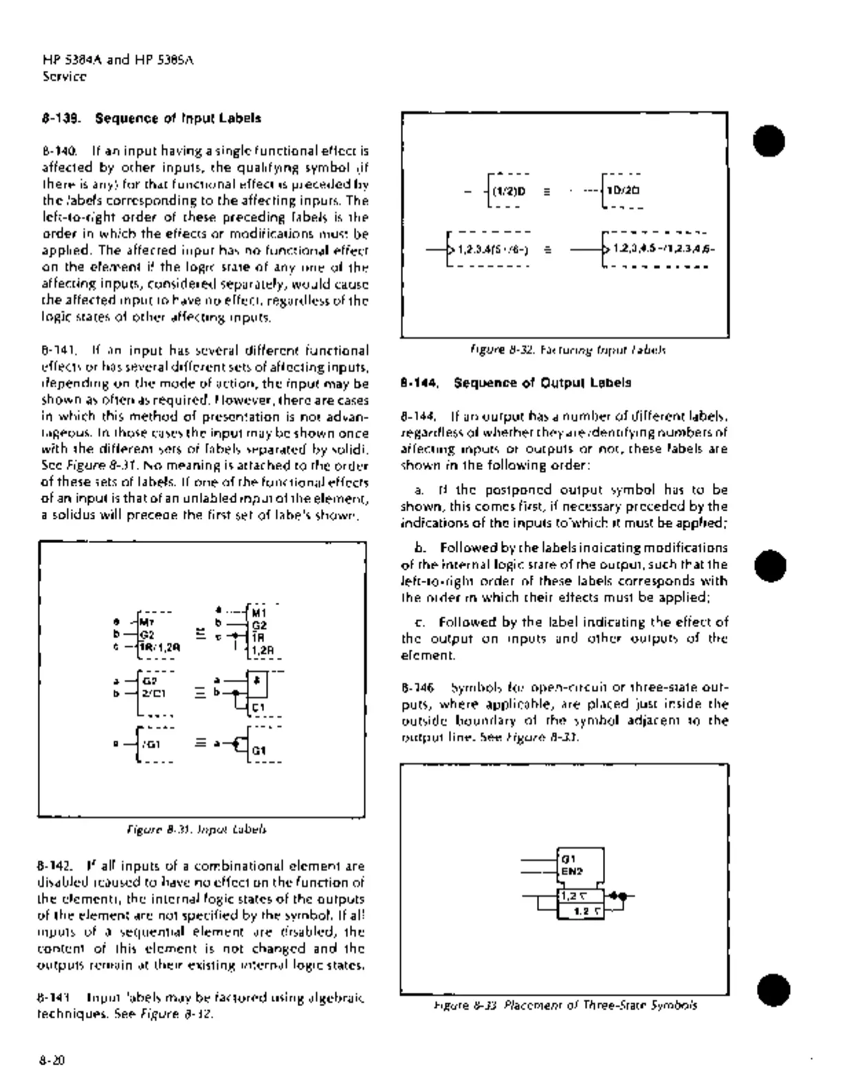
8-143.
Input
labels may be factored using algebraic
techniques.
See
Figure 8-32.
8-20
Figure
8-32.
Factoring
Input
Labels
8-144. Sequence
of
Output Labels
8-144.
If
an
output
has
a
number
of
different
labels,
regardless
of
whether
they
are
identifying
numbers
of
affecting inputs
or
outputs
or
not,
these labels are
shown
in
the
following
order:
a.
If
the postponed
output
symbol
has
to
be
shown, this comes first,
if
necessary
preceded
by
the
indications
of
the
inputs
to"which
it
must be
applied;
b.
Followed by the labels
indicating
modifications
of
the
internal
logic
state
of
the
outpuc
such that
the
left-to-right
order
of
these labels corresponds
with
the
order
in
which
their
effects must be
applied;
c.
Followed by
the
label
indicating
the
effect
of
the
output
on
inputs and
other
outputs
of
the
element.
8-146. Symbols
for
open-circuit
or
three-state
out-
puts,
where
applicable, are placed just inside
the
outside
boundary
of
the
symbol adjacent
to
the
output
line.
See
Figure 8-33.
Figure
8-33.
Placement
of
Three-State Symbols
•
•
•

 Loading...


