~!f:Jji'.
HP
5384A and
HP
5385A
svsTEMs
Installation
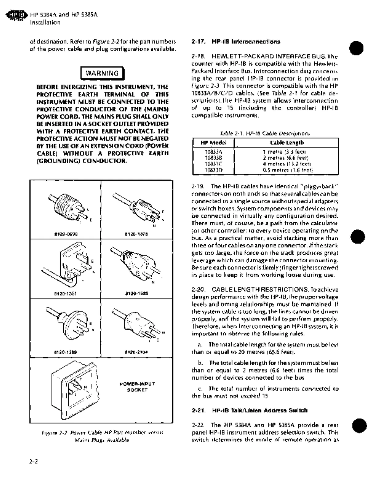
of
destination. Refer
to
Figure 2-2
for
the part numbers
of
the
power
cable and plug configurations available.
I
WARNING
I
BEFORE
ENERGIZING
THIS
INSTRUMENT,
THE
PROTECTIVE
EARTH
TERMINAL
OF
THIS
INSTRUMENT
MUST
BE
CONNECTED
TO
THE
PROTECTIVE
CONDUCTOR OF
THE
(MAINS)
POWER
CORD.
THE
MAINS
PLUG
SHALL
ONLY
BE
INSERTED
IN
A
SOCKET
OUTLET
PROVIDED
WITH
A
PROTECTIVE
EARTH
CONTACT.
THE
PROTECTIVE
ACTION
MUST
NOT
BE
NEGATED
BY
THE
USE
OF
AN
EXTENSION
CORD
(POWER
CABLE)
WITHOUT A
PROTECTIVE
EARTH
(GROUNDING) CON-DUCTOR.
2-2
E
8120-0698
8120-1351
N
8120-1369
N
8120-1378
L
N
8120-1689
~-
L E
8120-2104
POWER-INPUT
SOCKET
Figure 2-2. Power Cable HP
Part
Number
versus
Mains Plugs Available
2-17. HP-18 Interconnections
2-18.
HEWLETT-PACKARD
INTERFACE BUS. The
counter
with
HP-IB
is
compatible
with
the
Hewlett-
Packard Interface
Bus.
Interconnection
data
concern-
ing
the rear panel HP-IB
connector
is
provided
in
Figure 2-3. This
connector
is
compatible
with
the
HP
10833A/B/C/D
cables.
(See
Table
2-1
for
cable
de-
scriptions).The HP-IB system allows
interconnection
of
up
to
15
(including
the
controller)
HP-IB
compatible
instruments.
Table 2-1.
HP-18
Cable Descriptions
HP
Model Cable Length
10833A
1
metre
(3.3 feet)
108338 2 metres (6.6 feet)
10833C
4 metres (13.2 feet)
108330
0.5 metres (1.6 feet)
2-19. The HP-IB cables have identical
"piggy-back"
connectors
on
both
ends
so
that
several cables can
be
connected
to
a single source
without
special adapters
or
switch boxes. System
components
and devices may
be
connected
in
virtually any
configuration
desired.
There must,
of
course, be a path
from
the
calculator
(or
other
controller)
to
every device
operating
on
the
bus.
As
a practical matter, avoid stacking
more
than
three
or
four
cables
on
any
one
connector.
If
the
stack
gets
too
large,
the
force
on
the
stack produces great
leverage
which
can damage
the
connector
mounting.
Be
sure each
connector
is
firmly
(finger
tight)
screwed
in
place
to
keep
it
from
working
loose
during
use.
2-20.
CABLE
LENGTH
RESTRICTIONS.
To
achieve
design performance
with
the
HP-18,
the
proper
voltage
levels and
timing
relationships must be maintained.
If
the system cable
is
too
long, the lines cannot be driven
properly, and the system will fail
to
perform
properly.
Therefore, when interconnecting
an
HP-IB system, it
is
important
to
observe the
following
rules.
a.
The total cable length
for
the system must be
less
than
or
equal
to
20
metres
(65.6
feet).
b. The total cable length for the system must be
less
than
or
equal
to
2 metres
(6.6
feet) times
the
total
number
of
devices connected
to
the bus.
c.
The total
number
of
instruments connected
to
the bus must
not
exceed
15.
2-21. HP-18 Talk/Listen Address Switch
2-22.
The
HP
5384A
and
HP
5385A
provide
a rear
panel
HP-IB instrument address selection switch. This
switch determines the
mode
of
remote operation
as
•
•
•

 Loading...


