HP
5384A and
HP
5385A
Operation
and Programming
3-73. INPUTS
WARNING
I
DURING
BATTERY
OPERATION
WITH
THE
MAINS
POWER
CORD
DISCONNECTED
FROM
THE
MAINS
SUPPLY,
THE
FRONT
AND
REAR
PANELS
WILL
FLOAT
ATTHEVOLTAGEAPPLIED
TO
SIGNAL
COMMON
(INPUT
BNC
CON-
NECTOR
SHELL).
TO
AVOID
THE
RISK
OF
ELECTRIC
SHOCK
DURING
BATTERY
OPER-
ATION,
ENSURE
THE
VOLTAGE
APPLIED
TO
SIGNAL
COMMON
(BNC
SHELL)
DOES
NOT
EXCEED
42V
PEAK.
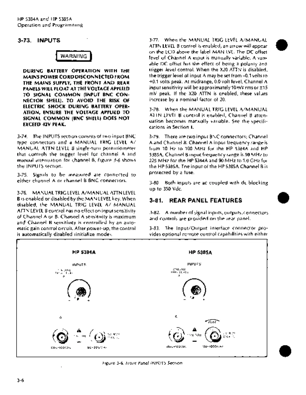
3-74. The INPUTS section consists
of
two
input
BNC
type connectors and a
MANUAL
TRIG
LEVEL
A/
MANUAL
ATTN
LEVEL
B
single-turn
potentiometer
that
controls
the
trigger
level
for
channel A and
manual
attenuation
for
channel
B.
Figure 3-6 shows
the
INPUTS section.
3-75. Signals
to
be measured are
connected
to
either
channel A
or
channel B BNC connectors.
3-76.
MANUAL
TRIG
LEVEL
A/MANUAL
ATTN
LEVEL
B
is
enabled
or
disabled by the
MAN
LEVEL
key.
When
disabled,
the
MANUAL
TRIG
LEVEL
A/
MANUAL
ATTN
LEVEL
B
control
has
no
effect
on
input
sensitivity
of
Channel A
or
B.
Channel A sensitivity
is
maximum
and Channel B sensitivity
is
controlled
by
an
auto-
matic gain
control
circuit.
After
power-up,
the
control
is
automatically disabled (initialize mode).
HP 5384A
INPUTS
r.1A:;UAL
!HI<>
ll
VH
A
A
tr::n
•,on
..I-
50•2251.'Hz
3-77.
When the
MANUAL
TRIG
LEVEL
A/MANUAL
ATTN
LEVEL
B control
is
enabled,
an
arrow
will appear
on
the LCD above the label
MAN
LVL.
The DC offset
level
of
Channel A
input
is
manually variable. A vari-
able
pc
offset
has
the effect
of
being a polarity and
trigger level control. When the
X20
ATTN
is
disabled,
the trigger level
of
input
A may be
set
from
-0.1 volts
to
+0.1
volts peak.
At
midrange,
0.0
volt level, Channel A
input
sensitivity will be approximately
10
mV
rms
or
±15
mV
peak.
If
the
X20
ATTN
is
enabled, these values
increase by a nominal factor
of
20.
3-78.
When
the
MANUAL
TRIG
LEVEL
A/MANUAL
ATTN
LEVEL
B
control
is
enabled, Channel B atten-
uation becomes manually variable.
See
the
specifi-
cations in Section
I.
3-79. There are
two
input
BNC connectors; Channel
A and Channel
B.
Channel A
input
frequency
range
is
from
10 Hz
to
100
MHz
for
the
HP
5384A and
HP
5385A.
Channel B
input
frequency
range
is
50
MHz
to
225
MHz
for
the
HP
5384A and
90
MHz
to
1.0 GHz
for
the
HP
5385A. The
input
of
the
HP
5385A Channel B
is
protected
by a fuse.
3-80. Both inputs are
ac
coupled
with
de
blocking
up
to
350
Vdc.
3-81. REAR PANEL FEATURES
3-82.
A
number
of
signal inputs, outputs, connectors
and controls are
provided
on
the rear panel.
3-83. The
Input/Output
interface
connector
pro-
vides
optional
remote
control
capabilities
with
either
HP 5385A
INPUTS
r.1ANUAL
IHIG
UV!l
A
A
tr:n
son
IOHz-IOOMHt
@~~;;~
'90·1000~.~Hz
Figure
3-6.
Front Panel INPUTS Section
3-6
•
•
•

 Loading...


