•
•
•
d.
Set
HP
8660C
to
output
a
100
MHz
sinewave,
varying the
HP
86603A
vernier
until
the
HP
436A
power
Meter
reads -24 dBm, ±0.3 dBm. Adjust A1R34
for
a stable display
of
100.00000
MHz,
±10 Hz.
e.
Vary
the
frequency
range
from
90
MHz
to
1000
MHz
and ver:fy the
HP
5385A
displays
the
correct
count.
f.
Turn the
HP
5385A and
the
HP
8660C
off
and
disconnect
all test
equipment.
5-19. Standard Oscillator
Adjustment
Procedures
5-20.
The
procedure
used
for
adjusting
the
standard
oscillator
is
the
same
as
the
procedure
used
for
ad-
justing
the
TCXO
at
25°C described
in
paragraph 5-23.
Refer
to
paragraph
5-23
for
adjustment
procedure.
5-21.
TCXO
Adjustment
Procedure
5-22. Two procedures are given
for
the adjustment
of
the TCXO (Temperature compensated Crystal
Ocsillator).
If
the
operation
of
the
counter
will be
solely at 25°C (77°F),
then
adjust
the
oscillator
fre-
quency
as
close
as
possible
to
10
MHz
using
the
procedure
in
paragraph
5-23.
If the operation
of
the
counter
will be over
the
full
temperature
range (0°C
to
40°C)
then
the
TCXO must be offset by
the
amount
HP
5384A and
HP
5385A
Adjustments
labeled on its cover
to
keep the TCXO
frequency
within
the manufacturers
frequency
specifications
over
the
temperature
range
of
0°C
to
40°C. In this
case
use the
procedure
in paragraph
5-28.
The TCXO
is
factory set
for
use near 25°C.
5-23.
Adjustment
of
the
TCXO at 25°C
NOTE
Allow
30
minutes
warm-up
time
for
the counter.
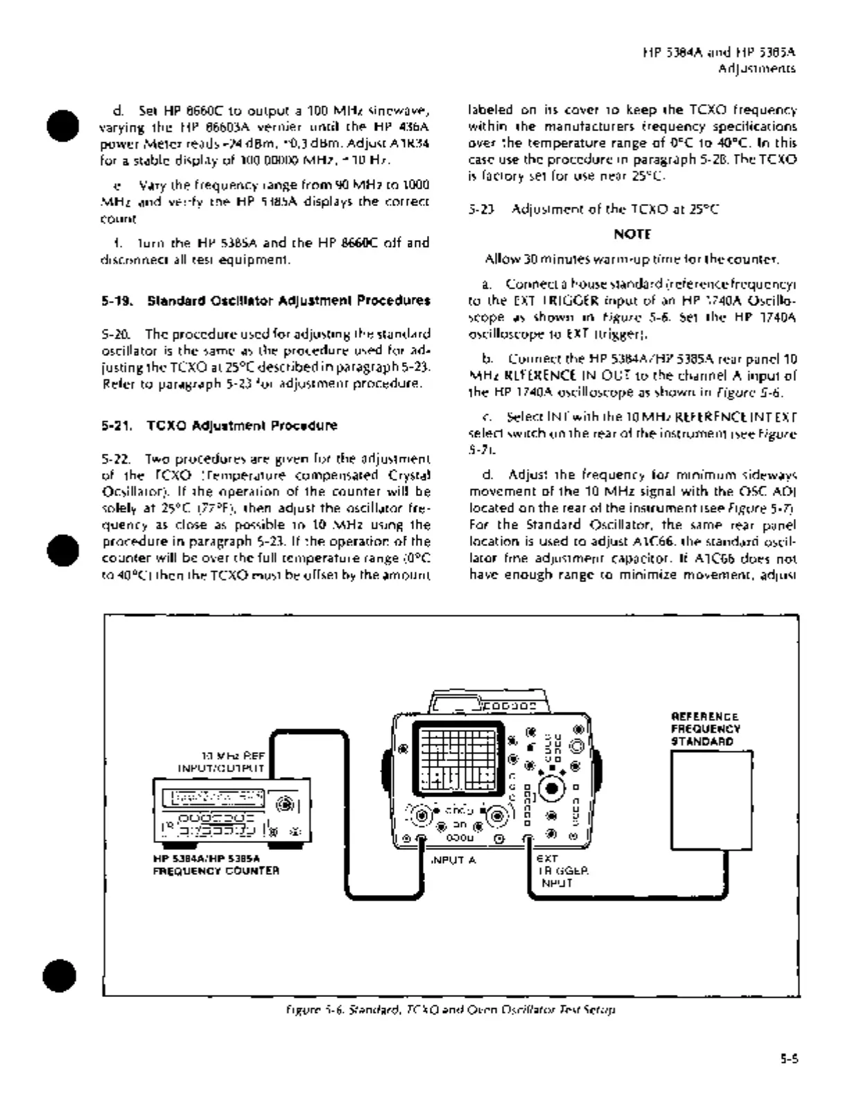
a.
Connect a house standard (reference frequency)
to
the
EXT
TRIGGER
input
of
an
HP
1740A Oscillo-
scope
as
shown in Figure 5-6.
Set
the
HP
1740A
oscilloscope
to
EXT
(trigger).
b.
Connect
the
HP
5384A/HP 5385A rear
panel10
MHz
REFERENCE
IN
OUT
to
the channel A
input
of
the
HP
1740A oscilloscope
as
shown in Figure 5-6.
c.
Select I NT
with
the
10
MHz
REFERENCE
I NT
EXT
select switch on the rear
of
the
instrument
(see
Figure
5-7).
d. Adjust
the
frequency
for
minimum
sideways
movement
of
the
10
MHz
signal
with
the OSC
ADJ
located on the rear
of
the
instrument
(see
Figure 5-7).
For
the
Standard Oscillator, the same rear panel
location
is
used
to
adjust A1C66, the standard oscil-
lator
fine
adjustment capacitor. If A1C66 does
not
have
enough
range
to
minimize
movement,
adjust
IL
\
~\oooooo
J.
REFERENCE
•
@DO@
FREQUENCY
@
@.
gg
©
STANDARD
10
MHz
REF
@@DO@
I
INPUT/OUTPUT
t
• • •
0 s •
0 0 ® 0
II
:000;::~::;7:2!
:·,:Hzill
~I
~
..--
0
gJ
0
I[Q)I~DIDIDDDjO
I
C@•
ooao
•@'J
B @ B
0
OD[D[OOD[D
@ @
@DO@
0 0
0 r.'l
DODO
0
(i.
@ 0
),
-
-
~
HP
5384A/HP 5385A
INPUT A
EXT
FREQUENCY
COUNTER TRIGGER
INPUT
Figure 5-6. Standard, TCXO
and
Oven
Oscillator Test
Setup
5-5

 Loading...


