HP
5384A and HP 5385A
Service
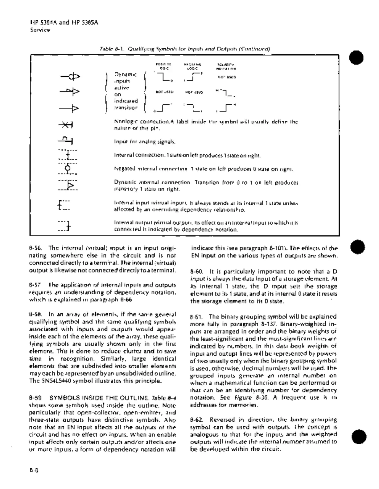
Table 8-3.
Qualifying
Symbols
for
Inputs
and
Outputs
(Continued)
POSITIVE
NEGATIVE
POLARITY
LOGIC
LOGIC
INDICATION
l
Dynamic
j
1
Lo
,So
NOT
USED
inputs
active
HLL
NOT
USED
NOT
USED
j
on
l
indicated
transition
oi
1
OL,
LSH
--ct>
~
--1>
*"l
~
~~J~~~
~~9~~~
Nonlogic
connection.A
label inside
the
symbol
will
usually
define
the
nature
of
this
pin.
Input
for
analog signals.
Internal
connection.
1 state
on
left
produces
1 state
on
right.
Negated
internal
connection.
1 state
on
left
produces
0 state
on
right.
~~J?:~
Dynamic
internal
connection.
Transition
from
0
to
1
on
left
produces
transitory
1 state
on
right.
Internal
input
(virtual
input).
It
always stands at its
internal
1 state unless
affected by
an
overriding
dependency
relationship:
Internal
output
(virtual
output).
Its
effect
on
an
internal
input
to
which
it
is
connected
is
indicated
by
dependency
notation.
8-56. The
internal
(virtual)
input
is
an
input
origi-
nating
somewhere
else
in
the
circuit
and
is
not
connected
directly
to
a
terminal.
The
internal
(virtual)
output
is
likewise
not
connected
directly
to
a terminal.
8-57. The application
of
internal inputs and
outputs
requires
an
understanding
of
dependency
notation,
which
is
explained
in
paragraph 8-66.
8-58.
In
an array
of
elements, if
the
same general
qualifying
symbol and
the
same
qualifying
symbols
associated
with
inputs and
outputs
would
appear
inside each
of
the
elements
of
the
array, these
quali-
fying
symbols are usually shown
only
in
the
first
element.
This
is
done
to
reduce
clutter
and
to
save
time
in
recognrtron. Similarly, large identical
elements
that are
subdivided
into
smaller elements
may each
be
represented
by
an
unsubdivided
outline.
The
SN54LS440
symbol illustrates this
principle.
8-59.
SYMBOLS
INSIDE
THE
OUTLINE.
Table 8-4
shows some symbols used inside
the
outline.
Note
particularly
that
open-collector,
open-emitter,
and
three-state
outputs
have distinctive symbols. Also
note
that
an
EN
input
affects all
the
outputs
of
the
circuit
and
has
no
effect on inputs.
When
an enable
input
affects
only
certain
outputs
and/or
affects
one
or
more
inputs, a
form
of
dependency
notation
will
8-8
indicate
this
(see
paragraph 8-101). The effects
of
the
EN
input
on
the
various types
of
outputs
are shown.
8-60.
It
is
particularly
important
to
note
that a D
input
is
always
the
data
input
of
a storage
element.
At
its
internal
1 state,
the
D
input
sets
the
storage
element
to
its 1 state, and at its
internal
0 state
it
resets
the
storage
element
to
its 0 state.
8-61. The
binary
grouping
symbol
will
be explained
more
fully
in
paragraph 8-137.
Binary-weighted
in-
puts are arranged
in
order
and
the
binary
weights
of
the
least-significant and
the
most-significant lines are
indicated
by
numbers. In this data
book
weights
of
input
and
outupt
lines
will
be
represented by powers
of
two
usually
only
when
the
binary
grouping
symbol
is
used, otherwise,
decimal
numbers
will
be
used. The
grouped
inputs
generate
an
internal
number
on
which
a mathematical
function
can be
performed
or
that can be
an
identifying
number
for
dependency
notation.
See
Figure 8-30. A
frequent
use
is
in
addresses
for
memories.
8-62. Reversed in
direction,
the
binary
grouping
symbol can be used
with
outputs. The
concept
is
analogous
to
that
for
the
inputs and
the
weighted
outputs
will
indicate
the
internal
number
assumed
to
be
developed
within
the
circuit.
•
•
•

 Loading...


