•
•
•
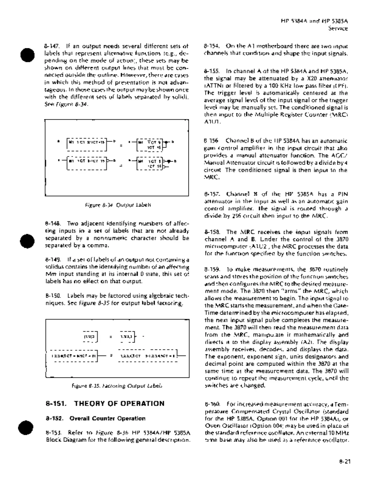
8-147. If
an
output
needs several
different
sets
of
labels that represent alternative
functions
(e.g.,
de-
pending
on
the
mode
of
action), these
sets
may be
shown
on
different
output
lines
that
must be
con-
nected outside the
outline.
However,
there
are
cases
in
which
this
method
of
presentation
is
not
advan-
tageous.
In those
cases
the
output
may be shown once
with
the
different
sets
of
labels separated by solidi.
See
Figure 8-34.
aiM~~:T~:1~~=~sJb
_
aiM~
~:~=:~c:~stb
_
a iMl-
TcT=91-.--
b
1CT=15
f-l
------
Figure
8-34.
Output
Labels
8-148.
Two adjacent
identifying
numbers
of
affec-
ting
inputs in a set
of
labels that are
not
already
separated by a
nonnumeric
character should be
separated by a comma.
8-149.
If
a set
of
labels
of
an
output
not
containing
a
solidus contains the identifying
number
of
an
affecting
Mm
input
standing
at
its internal 0 state, this set
of
labels
has
no
effect
on that
output.
8-150. Labels may be factored using algebraic tech-
niques.
See
Figure 8-35
for
output
label factoring.
'
Figure 8-35. Factoring
Output
Labels
8-151. THEORY OF OPERATION
8-152. Overall Counter Operation
8-153. Refer
to
Figure 8-36
HP
5384A/HP 5385A
Block Diagram
for
the
following
general description.
HP
5384A and
HP
5385A
Service
8-154.
On
the A 1
motherboard
there
are
two
input
channels that
condition
and shape
the
input
signals.
8-155.
In channel A
of
the
HP
5384A and
HP
5385A,
the
signal may be attenuated by a
X20
attenuator
(ATTN)
or
filtered
by a
100KHz
low
pass
filter
(LPF).
The
trigger
level
is
automatically centered at
the
average signal level
of
the
input
signal
or
the
trigger
level may be manually set. The
conditioned
signal
is
then
input
to
the
Multiple
Register
Counter
(MRC)
A1U1.
8-156. Channel B
of
the
H P 5384A
has
an
automatic
gain
control
amplifier
in
the
input
circuit
that also
provides a manual attenuator
function.
The
AGC/
Manual
Attenuator
circuit
is
followed
by a
divide
by 4
circuit. The
conditioned
signal
is
then
input
to
the
MRC.
8-157. Channel B
of
the
HP
5385A
has
a
PIN
attenuator
in the
input
as
well
as
an
automatic gain
control
amplifier. The signal
is
routed
through
a
divide
by
256
circuit
then
input
to
the MRC.
8-158. The
MRC
receives the
input
signals
from
channel A and
B.
Under
the
control
of
the
3870
microcomputer
(A 1 U2),
the
MRC
processes
the
data
for
the
function
specified by
the
function
switches.
8-159.
To
make measurements,
the
3870
routinely
scans
and stores
the
position
of
the
function
switches
and
then
configures the
MRC
to
the desired measure-
ment
mode. The
3870
then
"arms"
the
MRC,
which
allows the measurement
to
begin. The
input
signal
to
the
MRC
starts the measurement, and
when
the
Gate-
Time
determined
by the
microcomputer
has
elapsed,
the
next
input
signal pulse completes
the
measure-
ment. The
3870
will then read
the
measurement data
from
the MRC, manipulate
it
mathematically and
directs
it
to
the display assembly (A2). The display
assembly receives, decodes, and displays
the
data.
The
exponent,
exponent
sign, units designators and
decimal
point
are
computed
within
the
3870
at
the
same
time
as
the
measurement data. The
3870
will
continue
to
repeat the measurement cycle,
until
the
switches are changed.
8-160. For increased measurement accuracy, a Tem-
perature Compensated Crystal
Oscillator (standard
for
the
HP
5385A,
Option
001
for
the
HP
5384A),
or
Oven
Oscillator
(Option
004)
may be used
in
place
of
the
standard reference oscillator.
An
external10
MHz
time
base may also be used
as
a reference oscillator.
8-21

 Loading...


