•
•
•
8-25. Service Aids on Printed Circuit Boards
8-26. The servicing aids
include
test points,
tran-
sistor and integrated
circuit
designations,
adjustment
callouts, and assembly stock numbers.
8-27. After Service Safety Checks
8-28. Visually inspect
interior
of
instrument
for
any
signs
of
abnormal
internally
generated heat, such
as
discolored
printed
circuit
boards
or
components,
damaged insulation,
or
evidence
of
arcing.
Deter-
mine
and
remedy
cause
of
any such
condition.
8-29.
Using a suitable
ohmmeter,
check resistance
from
the
front
and rear panels
to
ground
pin
on
power
cord plug. The reading must be
less
than
one
ohm.
Flex
the
power
cord
while
making this measurement
to
determine
whether
intermittent
discontinuities
exist.
8-30. Check resistance
from
the
front
and rear panel
BNC
connector
shells and neutral (tied together)
with
the
power
switch
on
and
the
power
source discon-
nected. The
minimum
acceptable resistance
is
two
megohms. Replace any
component
which
results
in
a
failure .
8-31. Check line fuse(s)
to
verify
that
a
correctly
rated fuse
is
installed.
WARNING
TO
ASSURE
THE
INTEGRITY OF
THE
SAFETY
GROUNDING
CIRCUIT:
1.
Verify the
star
washer and rear panel BNC
connector nut are installed and securely
tightened.
2.
Verify the solder lug with green/yellow
wire (soldered to the A 1 board)
is
securely
fastened between potentiometer
R1
and
the front panel.
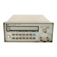
8-32. HP 5384A and HP 5385A Disassembly
Procedures
8-33. The
following
procedures describe
how
to
disassemble
the
HP
5384A and
HP
5385A counters.
a.
Remove
the
two
plastic feet
from
the
bottom
rear
of
the
counter.
The removal instructions are
molded
into
the
bottom
of
each
foot.
b. Remove
the
dark
green adhesive strips
on
each
side near
the
front
of
the
instrument.
HP 5384A and HP 5385A
Service
c. Remove
four
6-32 screws
from
the
bottom
cover
of
the
instrument.
d.
Gently
lift
the
top
cover
up
and
off
the
instrument.
8-34.
If
there
is
an interface
board
in
the
instrument,
follow
the
next
three
steps
for
disassembly. If
there
is
no
interface board present, skip
the
following
three
steps and
continue
with
step
"h".
e.
Disconnect
the
ribbon
cable
from
the
mother
board.
f.
Remove
the
two
screws
on
the
rear panel that
hold
it
in
place.
g.
Remove
the
interface board
from
the
instru-
ment
by pressing in
the
plastic catch near
the
top
of
the
support
post and
lifting
up
on
the
board.
h. Remove
two
6-32 screws that
hold
the
mother-
board
to
the
bottom
cover.
Gently
lift
the
mother-
board
from
the
bottom
cover. The
front
and rear
panels
will
remain attached
to
the
motherboard.
8-35. Assembly Identification
8-36. The name, assembly
number,
and
Hewlett-
Packard part
number
of
the HP 5384A and
HP
5385A
assemblies are listed in Table 8-1.
·
Table
8-1.
Assembly Usage
REF.
PART
NAME
HP
PART
DES.
NUMBER
A1
Main Board Assembly 05384-60001
A1
Main Board Assembly,
TXCO
(Opt.
001)
05384-60006
A1
Main
Board Assembly,
Oven
Osc.
(Opt.
004)
05384-60007
A1
Main Board Assembly,
05385-60001
(TCXO
Std)
A1
Main Board Assembly,
Oven
Osc.
(Opt.
004) 05385-60003
A2
Display Assembly
Keyboard Assembly
05384-60102
Liquid Crystal Display
Assembly
05384-60104
A3
Battery Pack Assembly 05384-60003
A4
HP-IL Board Assembly 05006-60004
AS
HP-IB Board Assembly 05384-60005
8-3

 Loading...