•
•
•
HP
5384A
and
HP
5385A~!j:J!i'.
Installation svSTEMS
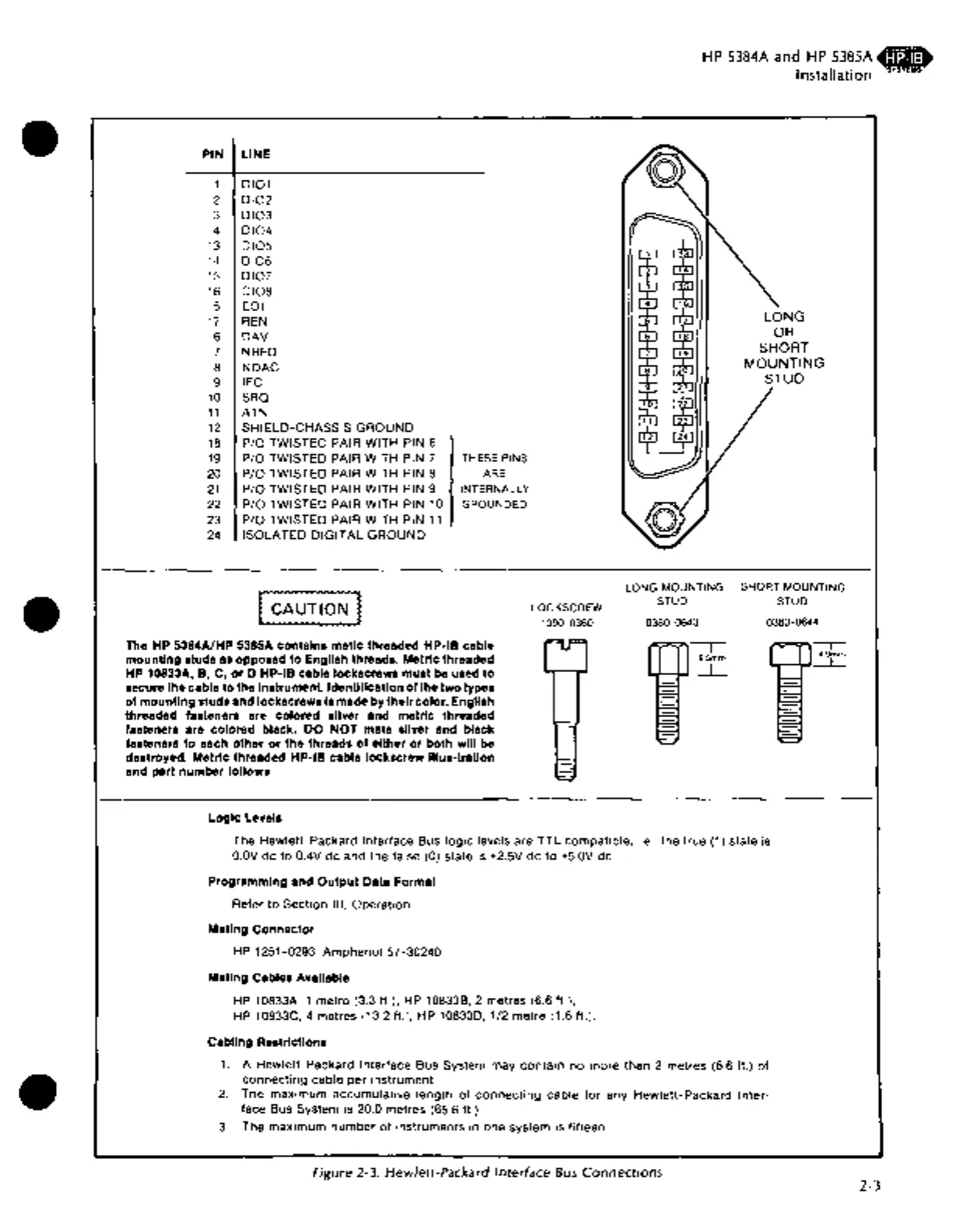
PIN
LINE
1
DI01
2
DI02
3
DI03
4
DI04
13
DI05
14
DI06
15
DI07
16
DI08
5 EOI
17
REN
6
DAV
7 NRFD
8
NDAC
9
IFC
10
SRQ
11
ATN
12
SHIELD-CHASSIS GROUND
18
P/0
TWISTED PAIR WITH PIN 6
19
P/0
TWISTED PAIR WITH PIN 7
THESE PINS
20
P/0
TWISTED PAIR WITH PIN 8
ARE
21
P/0
TWISTED PAIR WITH PIN 9
INTERNALLY
22
P/0
TWISTED PAIR WITH PIN 10
GROUNDED
23
P/0
TWISTED PAIR WITH PIN
11
24
ISOLATED DIGITAL GROUND
LONG MOUNTING SHORT MOUNTING
STUD STUD
LOCKSCREW
1390-0360
0380-0643 0380-0644
The HP 5384A/HP 5385A contains metlc threaded HP-18 cable
mounting
studs as opposed to English threads. Metric threaded
HP 10833A,
8,
C,
or
D HP-18 cable lockscrews must be used
to
secure the cable to the Instrument. Identification
of
the
two
types
of
mounting
studs and lockscrews Is made
by
their
color. English
threaded fasteners are colored sliver and metric threaded
fasteners are
colored black. DO
NOT
mate sliver and black
fasteners to each
other
or
the threads
of
either
or
both will be
destroyed. Metric threaded
HP-18 cable lockscrew
lllus-trallon
and part number follows.
Logic Levels
-----r
6.5mm
~
The Hewlett-Packard Interface Bus
logic
levels are
TTL
compatible, i.e., the true (1) state is
O.OV
de to 0.4V de and the false (0) state
is
+2.5V de
to
+5.0V de.
Programming and
Output
Data Format
Refer to Section
Ill,
Operation
Mating Connector
HP 1251-0293; Amphenol
57-30240.
Mating Cables Available
HP 10833A, 1 metre (3.3 ft.), HP 10833B, 2 metres (6.6 ft.),
HP
10833C, 4 metres (13.2 ft.), HP 108330, 1/2 metre (1.6 ft.).
Cabling Restrictions
1.
A Hewlett-Packard Interface Bus System may contain no more than 2
r:netres
(6.6 ft.)
of
connecting cable per instrument.
2.
The maximum accumulative length
of
connecting
cable
for
any Hewlett-Packard Inter-
face Bus System is 20.0 metres (65.6 ft.).
3.
The maximum number
of
instruments
in
one system is fifteen.
Figure 2-3. Hewlett-Packard Interface
Bus
Connections
-.
4.9mm
___l_
2-3

 Loading...


