•
•
•
f.
This completes the adjustment
of
the
standard
oscillator
or
the TCXO
for
use near 25°C.
5-24.
Adjustment
Of
The TCXO
With
Offset (0°
to
400C):
a.
To
observe
the
offset stamped on
the
label
of
the TCXO, remove the
top
cover by
removing
the
four
screws located
in
the
bottom
half
of
the
cabinet.
For
acccess
to
the
two
screws at
the
rear
of
the
counter,
remove the rear feet. Lift
off
the
top.
b.
Connect a house standard (reference frequency)
to
Channel A
of
the
HP
5384A/HP 5385A
as
shown in
Figure 5-6.
c.
Cycle
the
HP
5384A/HP 5385A
from
STBY
to
ON.
Press
the
DISPLAY DIGITS
"up"
(O)
key once.
NOTE
Allow
30
minutes
warm-up
time
for
the
counter.
d. Adjust
the
TCXO
frequency
to
10
MHz
±the
offset labeled
on
the TCXO. For example,
if
the offset
is
+3.5 Hz
(3.5
Hz above
10
MHz),
then
the
TCXO
should be adjusted
so
the
10
MHz
input
frequency
appears
to
be
9.9999965
MHz
(which
is
3.5
Hz
below
the
TCXO frequency)
on
the
counter
display at a
room
temperature
of
25°C.
e.
Reinstall
the
covers; the TCXO offset adjust-
ment
is
completed.
5-25. Oven Oscillator Adjustment Procedure
a.
Remove the
top
cover by removing
the
four
screws located
in
the
bottom
half
of
the cabinet. (For
access
to
the
two
screws
at
the
rear
of
the
counter,
remove the rear feet.) Lift
off
the
top.
b.
The
HP
5384A/HP
5385A
should
now
be allowed
to
operate
for
at least
30
minutes
before
proceeding
with
the
oscillator adjustment.
A3
A3W1
IRED
I
10!1
20W
RESISTOR
0811-1655
A3W2
1BLACK1
HP
5384A and
HP
5385A
Adjustments
c.
Connect
a house standard (reference
fre-
quency)
to
the
EXT
TRIGGER
input
of
an
HP
1740A
oscilloscope
as
shown
in
Figure 5-6.
Set
the
1740A
Oscilloscope
to
External Trigger.
d.
Connect
the
HP
5384A/HP 5385A rear
panel10
MHz
REFERENCE
IN
OUT
to
the Channel A
input
of
the
HP
1740A oscilloscope
as
shown in Figure 5-6.
e.
Turn
the
adjustment screw on the oven oscil-
lator
for
minimum
sideways
movement
of
the
signal
on
the
oscilloscope.
f.
By
timing
the
sideways
movement
(in
em/
second),
the
approximate offset can be
determined
based
on
the
HP
1740A oscilloscope sweep speed
as
shown in Table 5-2.
g.
This completes the adjustment
of
the oven
oscillator.
5-26. HP 5384AIHP 5385A Battery Charger
Adjustment Procedure
5-27.
The A3 battery charger board requires adjust-
ment
if
U1, U2,
or
Q1 have been replaced.
5-28.
To
perform
the
battery charger adjustments,
make the
following
preparations:
a.
Remove the
top
cover and place
to
the
right
of
the
counter. Leave
the
battery charger
circuit
con-
nected (via
ribbon
cable W2).
b.
Disconnect
A3B1
6-volt battery
from
the
circuit
by removing A3W1 and A3W2
from
the battery.
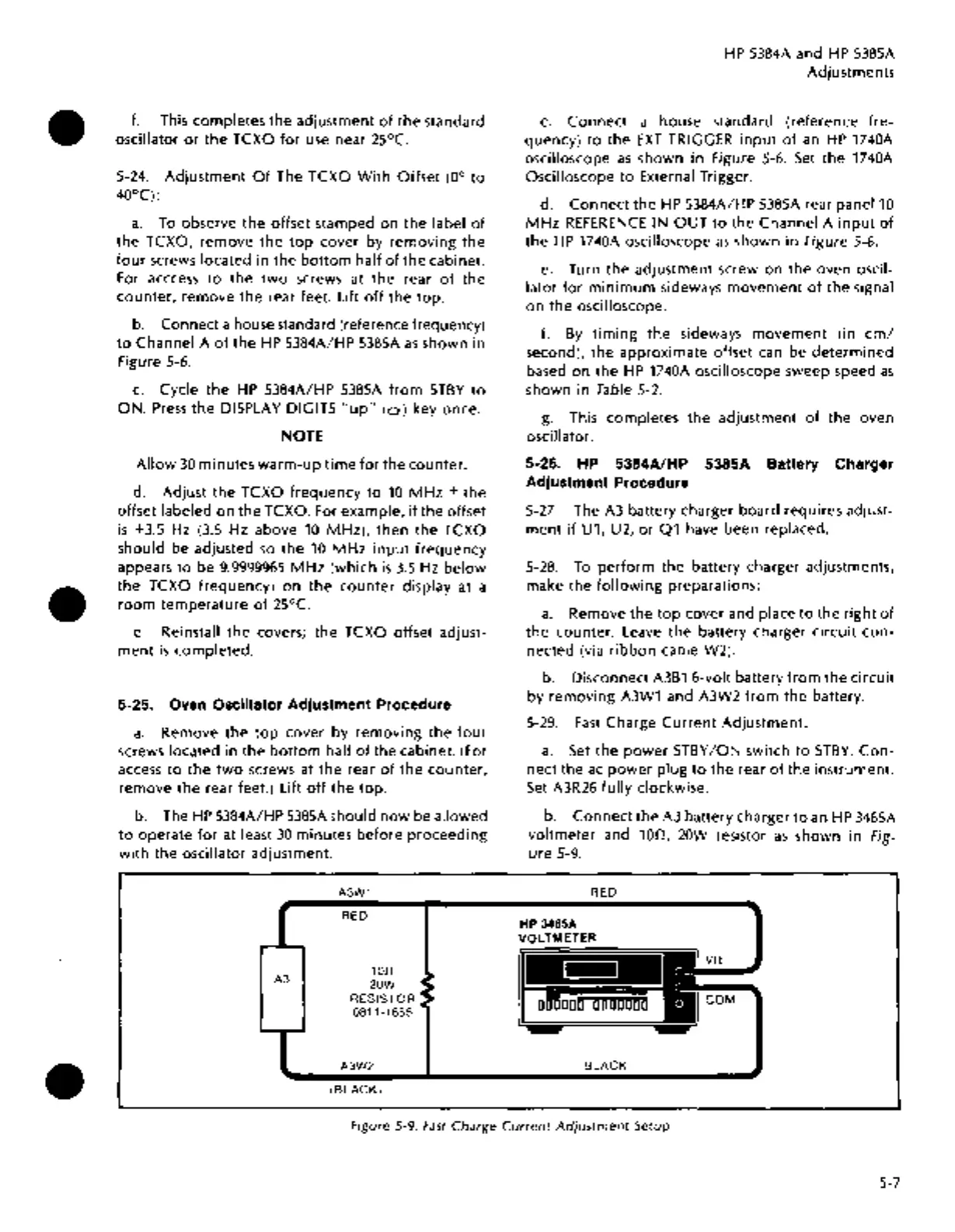
5-29.
Fast
Charge
Current
Adjustment:
a.
Set
the
power
STBY
/ON
switch
to
STBY.
Con-
nect
the
ac
power
plug
to
the rear
of
the
instrument.
Set
A3R26
fully
clockwise.
b.
Connect
the A3 battery charger
to
an
HP
3465A
voltmeter
and
100,
20W resistor
as
shown in Fig-
ure
5-9.
RED
HP 3465A
VOLTMETER
BLACK
Vll
COM
Figure 5-9.
Fast
Charge
Current
Adjustment
Setup
5-7

 Loading...


