•
•
HP
5384A and
HP
5385A
Installation
SECTION
II
INSTALLATION
2-1. INTRODUCTION
2-2. This section contains
information
for
unpack-
ing, inspection, storage, and installation.
2-3. UNPACKING AND INSPECTION
2-4.
If
the
shipping
carton
is
damaged, inspect
the
instrument
for
visible damage (scratches, dents, etc.).
If
the
instrument
is
damaged,
notify
the
carrier and
the
nearest Hewlett-Packard
Sales
and Service
Office
immediately
(offices are listed
at
the
back
of
this
manual). Keep
the
shipping and packing material
for
the carrier's inspection. The Hewlett-Packard
Sales
and Service
Office
will
arrange
for
repair
or
replace-
ment
of
your
instrument
without
waiting
for
the
claim
against
the
carrier
to
be settled.
2-5. PREPARATION FOR USE
[~
Before connecting the instrument to
ac
power lines, be
sure
that the voltage selector
is
properly positioned
as
described below.
2-6.
POWER
REQUIREMENTS
2-7. The
counter
has
the
following
ac
power
requirements:
115V, +10%, -25%, 48-66 Hz single phase
230V, +10%, -15%, 48-66 Hz single phase
115V, +10%, -10%, 380-420 Hz single phase
A2-8.
LINE VOLTAGE SELECTION
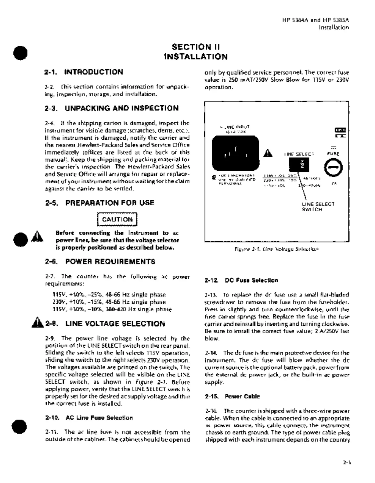
2-9. The
power
line
voltage
is
selected by
the
position
of
the
LINE
SELECT
switch
on
the rear panel.
Sliding the switch
to
the
left
selects 115V
operation,
sliding
the
switch
to
the
right
selects
230V
operation.
The voltages available are
printed
on
the
switch. The
specific voltage selected
will
be visible
on
the
LINE
SELECT
switch,
as
shown in Figure 2-1. Before
applying
power,
verify
that
the
LINE
SELECT
switch
is
properly
set
for
the
desired ac supply voltage and that
the
correct
fuse
is
installed.
2-10.
AC
Line
Fuse
Selection
2-11. The
ac
line
fuse
is
not
accessible
from
the
outside
of
the
cabinet. The cabinet
should
be
opened
only
by
qualified
service personnel. The
correct
fuse
value
is
250
mAT/250V Slow Blow
for
115V
or
230V
operation.
-LINE
INPUT
18
VA
r.1AX
f
f ! I
®
~~~
~~sg~:z~~~~6
PERSONNEL
A LINE SELECT
FUSE
e
2A
LINE SELECT
SWITCH
Figure
2-1.
Line Voltage Selection
2-12. DC
Fuse
Selection
2-13.
To
replace the de fuse
use
a small flat-bladed
screwdriver
to
remove the fuse
from
the fuseholder.
Press
in slightly and turn counterclockwise, until the
fuse carrier springs free. Replace the fuse in the fuse
carrier and reinstall by inserting and
turning
clockwise.
Be
sure
to
install the correct fuse value; 2
N250V
fast
blow.
2-14.
The de fuse
is
the main protective device
for
the
instrument. The de fuse will
blow
whether
the
de
current source
is
the optional battery pack,
power
from
the external
de
power
jack,
or
the
built-in
ac
power
supply.
2-15.
Power
Cable
2-16.
The counter
is
shipped
with
a three-wire
power
cable.
When
the cable
is
connected
to
an
appropriate
ac
power source, this cable connects the instrument
chassis
to
earth ground. The type
of
power
cable
plug
shipped
with
each instrument depends
on
the
country
2-1

 Loading...


