•
•
•
HP 5384A and
HP
5385A
Adjustments
SECTION V
ADJUSTMENTS
5-1.
INTRODUCTION
5-2.
This section describes the adjustments
required
to
maintain
the
HP
5384A/HP 5385A
operating
char-
acteristics
within
specifications. Adjustments should
be made
when
required,
such
as
after a
performance
test failure
or
when
components
are replaced that
may affect
an
adjustment.
5-3.
Table
5-1
lists
the
adjustment procedures, in
the
recommended
order
of
performance,
and indicates
the
adjustable
components
involved.
5-4. EQUIPMENT REQUIRED
5-5.
The test
equipment
required
for
the
adjustment
procedures
is
listed in Table 1-4, Recommended
Test
Equipment. Substitute instruments may be used
if
they
meet
the
critical specifications.
5-6.
ADJUSTMENT
LOCATIONS
5-7.
Adjustment
locations are
identified
in
the
procedure
for
each adjustment.
5-8. SAFETY CONSIDERATIONS
5-9.
This section contains warnings that must be
followed
for
your
protection
and
to
avoid damage to
the
instrument.
WARNING I
MAINTENANCE
DESCRIBED
HEREIN
IS
PER-
FORMED
WITH
POWER
SUPPLIED
TO
THE
INSTRUMENT AND
PROTECTIVE
COVERS
RE-
MOVED. SUCH MAINTENANCE SHOULD
BE
PERFORMED
ONLY
BY
SERVICE-TRAINED
PERSONNEL
WHO
ARE
AWARE
OF
THE
HAZARDS
INVOLVED
(FOR
EXAMPLE,
FIRE
AND
ELECTRICAL
SHOCK),
WHERE
MAIN-
TENANCE
CAN
BE
PERFORMED WITHOUT
POWER
APPLIED,
SHOULD
BE
REMOVED.
BEFORE
ANY
REPAIR
IS
COMPLETED,
ENSURE
THAT
ALL
SAFETY
FEATURES
ARE
INTACT AND
FUNCTIONING, AND THAT
ALL
NECESSARY
PARTS
ARE
CONNECTED TO
THEIR
PRO-
TECTIVE
GROUNDING MEANS.
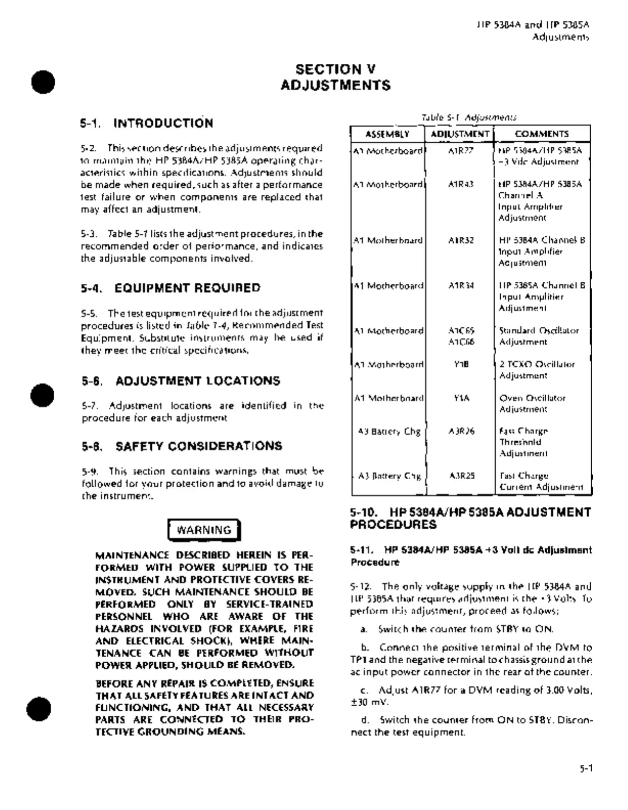
Table
5-1.
Adjustments
ASSEMBLY
ADJUSTMENT
COMMENTS
A1
Motherboard
A1R77 HP
5384A/HP
5385A
+3
Vdc
Adjustment
A 1
Motherboard
A1R43 HP
5384A/HP
5385A
Channel
A
Input
Amplifier
Adjustment
A 1
Motherboard
A1R32
HP 5384A
Channel
B
Input
Amplifier
Adjustment
A 1
Motherboard
A1R34 HP 5385A
Channel
B
Input
Amplifier
Adjustment
A 1
Motherboard
A1C65
Standard
Oscillator
A1C66
Adjustment
A 1
Motherboard
Y1B
2 TCXO
Oscillator
Adjustment
A 1
Motherboard
Y1A
Oven
Oscillator
Adjustment
A3
Battery
Chg
A3R26
Fast
Charge
Threshold
Adjustment
A3
Battery
Chg
A3R25
Fast
Charge
Current
Adjustment
5-10. HP 5384A/HP 5385AADJUSTMENT
PROCEDURES
5-11. HP 5384A/HP 5385A
+3
Volt de
Adjustment
Procedure
5-12. The
only
voltage supply
in
the
HP
5384A and
HP
5385A
that
requires adjustment
is
the +3 Volts.
To
perform
this adjustment, proceed
as
follows:
a.
Switch the
counter
from
STBY
to
ON.
b.
Connect
the positive
terminal
of
the
DVM
to
TP1
and the negative
terminal
to
chassis
ground
at
the
ac
input
power
connector
in the rear
of
the
counter.
c.
Adjust
A1R77
for
a
DVM
reading
of
3.00
Volts,
±30 mV
..
d. Switch
the
counter
from
ON
to
STBY.
Discon-
nect
the
test
equipment.
5-1

 Loading...


