•
•
•
be displayed
until
the
RESET
/LOCAL
key
is
pressed
or
a DCL (device clear)
command
is
sent
to
the
counter
by
the
controller.
Illegal
commands
can
either
be
commands
not
recognizable
to
the
counter
or
com-
mands
which
are recognizable,
but
are
invalid
if
the
counter
is
in
the
diagnostic
or
talk
only
modes.
3-33.
Instrument
error
messages are listed in Ta-
ble 3-2.
Table 3-2. Error Messages
Error
Messages
10
Self-test error
50
Unrecognizable mnemonic in command
51
Illegal numeric
in
command
52
First
character of command
is
illegal
53
Illegal character
in
the "DR" (remote display)
command
55
Invalid
HP
5384A/85A
command or
HP-IL
protocol or frame error
56
Invalid diagnostic command
60
ROM
failure in
1/0
processor
61
RAM
failure
in
1/0
processor
70
Controller connected to talk-only instrument
3-34.
If
the
fuse in
the
Channel
B
input
opens,
the
message
"INPUT
ERROR"
will
appear on
the
display.
3-35. FRONT PANEL FEATURES
3-36. The
front
panel controls, indicators, and
con-
nectors are
shown
in
Figures 3-7
through
3-9.
3-37. The
following
paragraphs describe
the
general
purpose and use
of
the
operator
keys and controls.
They are discussed by
functional
grouping,
as
follows:
a.
ON/STBY
b.
A CHANNEL
c.
B CHANNEL and A&B
d.
GATE
and DISPLAY DIGITS
e.
RESET
/LOCAL
and CHECK
f.
INPUTS
3-38. ON/STBY
3-39. The ON/STBY switch connects
or
disconnects
the
output
from
the
+5-volt
supply
to
the
rest
of
the
instrument.
It
does
not
control
the
ac
power
line
at
the
primary
of
the
power
transformer.
If
Option
004,
the
ovenized
oscillator
is
installed,
+S
volts
is
supplied
HP 5384A
and
HP 5385A
Operation
and
Programming
to
the
oscillator
whether
the
power
switch
is
in
the
STBY
(standby)
mode
or
in
the
ON
mode
(with
the
ac
power
cord
or
external de
connected).
Figure
3-1
shows
the
ON/STBY switch.
POWER 1
.L
STBY
g
_._
O~J
Figure 3-1. Front Panel ON/STBY Switch
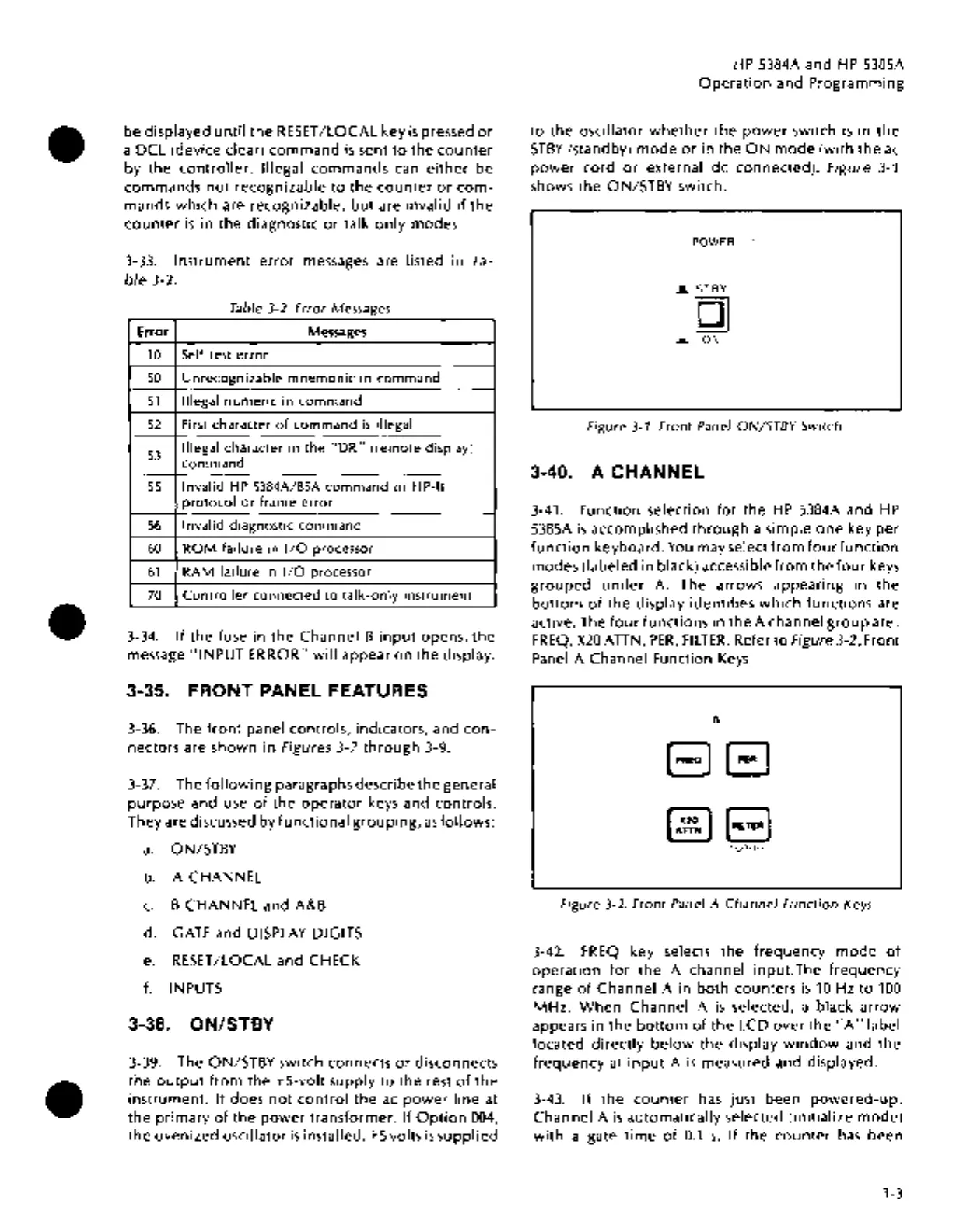
3-40. A CHANNEL
3-41. Function selection
for
the
HP
5384A and
HP
5385A
is
accomplished
through
a simple
one
key
per
function
keyboard.
You
may select
from
fourfunction
modes (labeled in black) accessible
from
the
four
keys
grouped
under
A. The arrows appearing in
the
bottom
of
the
display
identifies
which
functions
are
active. The
four
functions
in
the
A channel
group
are:
FREQ,
X20
ATIN,
PER,
FILTER.
Refer
to
Figure 3-2, Front
Panel
A Channel Function
Keys.
A
EJEJ
~B
lOOk
H.·
Figure 3-2. Front Panel A
Channel
Function
Keys
3-42.
FREQ
key selects
the
frequency
mode
of
operation
for
the
A channel
input.The
frequency
range
of
Channel
A in
both
counters
is
10
Hz
to
100
MHz.
When
Channel A
is
selected, a black
arrow
appears in
the
bottom
of
the
LCD
over
the"
A"
label
located
directly
below
the
display
window
and
the
frequency
at
input
A
is
measured and displayed.
3-43.
If
the
counter
has
just
been
powered-up,
Channel A
is
automatically selected
(initialize
mode)
with
a gate
time
of
0.1
s.
If
the
counter
has
been
3-3

 Loading...


