I
-
I
-
Creating
a
user
flatness
array
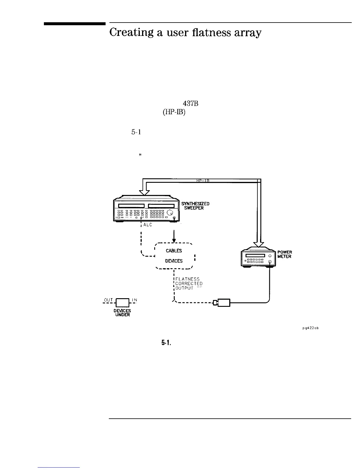
In this example an HP
437B
power meter controlled by the sweeper through
the interface bus
(HP-IB)
is used to enter the correction data into a flatness
array.
Figure 5-l shows a typical system setup. The setup shown assumes that if
the setup has an external leveling configuration, that the steps necessary to
correctly level have been taken. Refer to Chapter 2, “Externally Leveling the
Sweeper,
))
for information on external leveling.
;ALC
IN
I
RF
I
OUTPUT
I
1
INPUT
1
PORT
I
;
--------.
I
I
I
CAmEs
I
----d
AND OTHER
;
i
DO/ICES
,
*-
-
-
-,--
--’
IFLATNESS
CORRECTED
,OUTPUT
TEST PORT
-0-uq-J-N
----------
i
.-----,--,
“l%tE”E::
POWER SENSOR
TEST
Figure
5.1.
Creating a User Flatness Array
5-3
 Loading...