I
-
I
-
Creating User Flatness Arrays
Creating a user flatness array
To
set
up
the
sweeper
1.
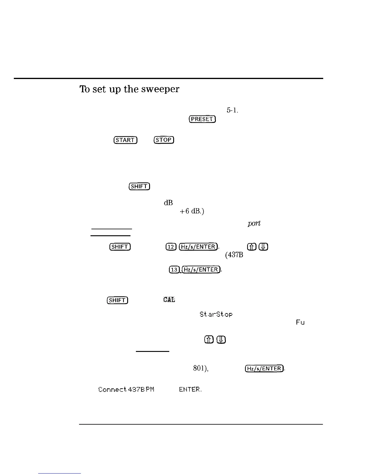
Connect the equipment as shown in Figure 5-l. Do not connect the power
sensor to the system yet. Press
(PRESET)
on the sweeper.
2.
3.
If a frequency range other than the full range of the instrument is desired,
use the
CSTART)
and
m
keys to input the desired frequency range.
If external cables and/or devices are used between the sweeper leveling
point (the RF OUTPUT if internally leveled, or the coupler/splitter output
if externally leveled) and the remote test port, the nominal (average) loss
of these components should be entered as an offset. To enter the power
offset, press
(SHIFT)
OFFSET (in the POWER key group) and then enter the
nominal loss from the leveling point of the sweeper to the test port. (For
example, if there is a 6
dB
loss from the leveling point to the remote test
port, enter a power offset of
+6
dB.)
4.
Set the power level to the level desired at the test
purt
by pressing,
[POWER LEVEL) and entering the desired number.
5.
Select
[ml
SPECIAL
112)
(jj).
Use the @j
@J
keys to select
the type of power meter you will be using.
(437B
for this example.)
6.
Select (SHIFT) SPECIAL
113)
(w’.
Enter the HP-IB address of the
power meter you will be using for the calibration. (Thirteen is the default
address for power meters.)
7.
Press
[%iW)
FLTNESS
CAL
a. Select whether to calibrate over
S?.at-:~t,op
(correction points will be
linearly spaced over the selected Start/Stop frequency range, or
Fu
11
Bard (correction points will be linearly spaced over the full frequency
range of the instrument). Use the
m
Q)
keys to make your selection,
then press [Hz/s/ENTER).
b. Select the number of correction points, using the keypad for your entry
(valid entries range from 2 to Sol), then press
I-1.
c. The MARKER/SWEEP/STATUS display should now read:
Conned.
437B
PM
--
EHTER.
5-4
 Loading...