MODEL 8559A
ADJUSTMENTS
ADJUSTMENTS
-
-
5
-
17.
POWER SUPPLY CHECKS AND ADJUSTMENTS
REFERENCE:
A7,
A8, A9 Schematics
DESCRIPTION:
The
+
14.5V and
-
10V regulated power supplies on Frequency Control Assembly A7 are adjusted. The
(dependent)
-
12V power supply is then checked for proper dc output (with less than
+
50 mV variation) while
the spectrum analyzer is tuned from 10 MHz to
3
GHz. The
+
10V power supply on Sweep Generator/Band-
width Control Assembly A9 and the VO (Varactor Offset) voltage on Marker Assembly A8 are then adjusted.
Both the
+
10V power supply voltage and the VO voltage are temperature
-
dependent and must be adjusted
during the first five minutes after the spectrum analyzer is turned on (cold instrument).
DIGITAL VOLTMETER
Dl SPLAY
CABLE
ASSEMBLY
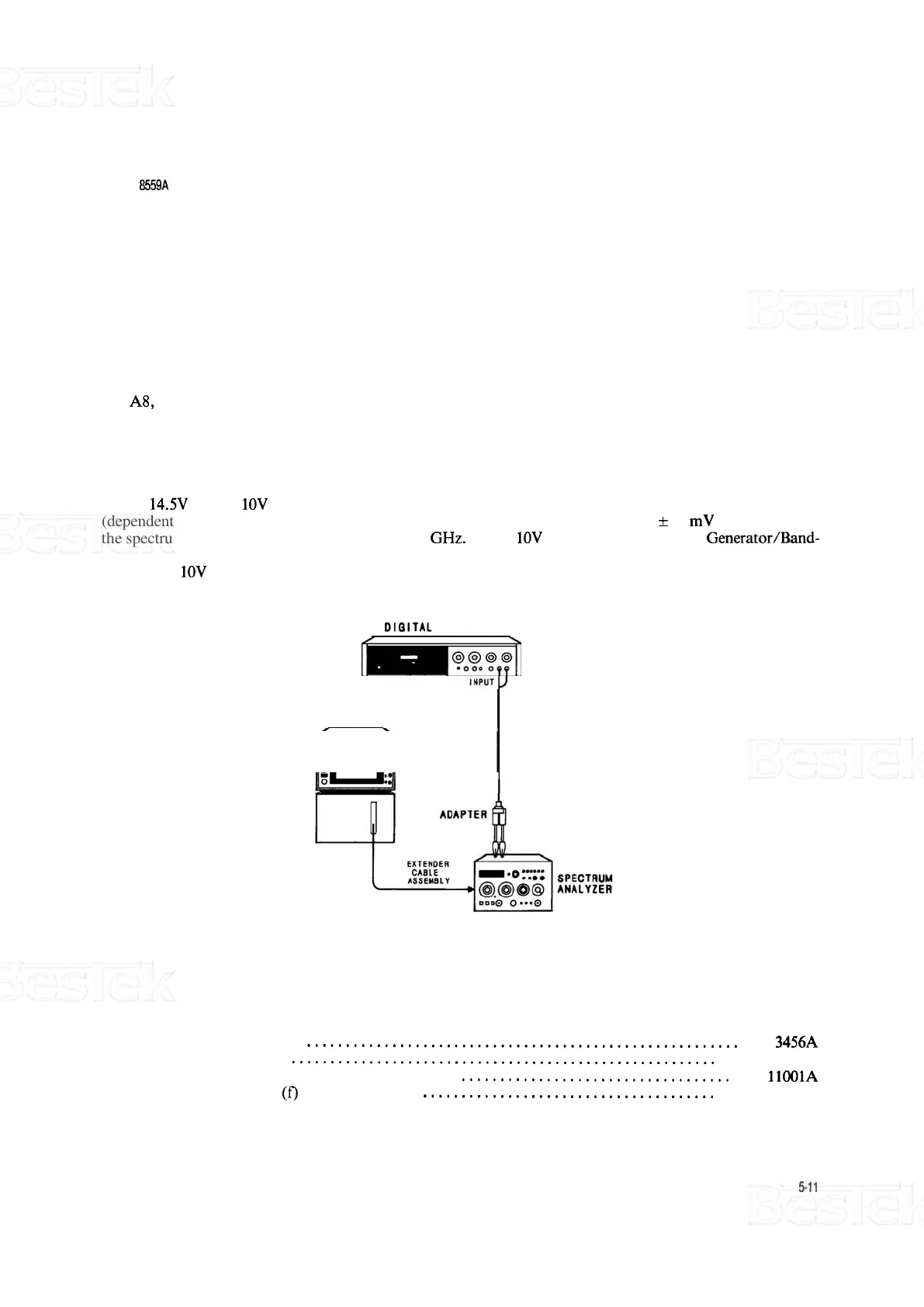
FIGURE 5
-
1. POWER SUPPLY CHECKS AND ADJUSTMENTS TEST SETUP
EQUIPMENT:
Digital Voltmeter
........................................................
HP
3456A
Extender Cable
.......................................................
HP
5060
-
0303
Cable Assembly, BNC (m) to Banana Plug
...................................
HP
11001A
Adapter, BNC
(f)
to Alligator Clips
......................................
HP
8120
-
1292

 Loading...


