MODEL 8559A
SERVICE
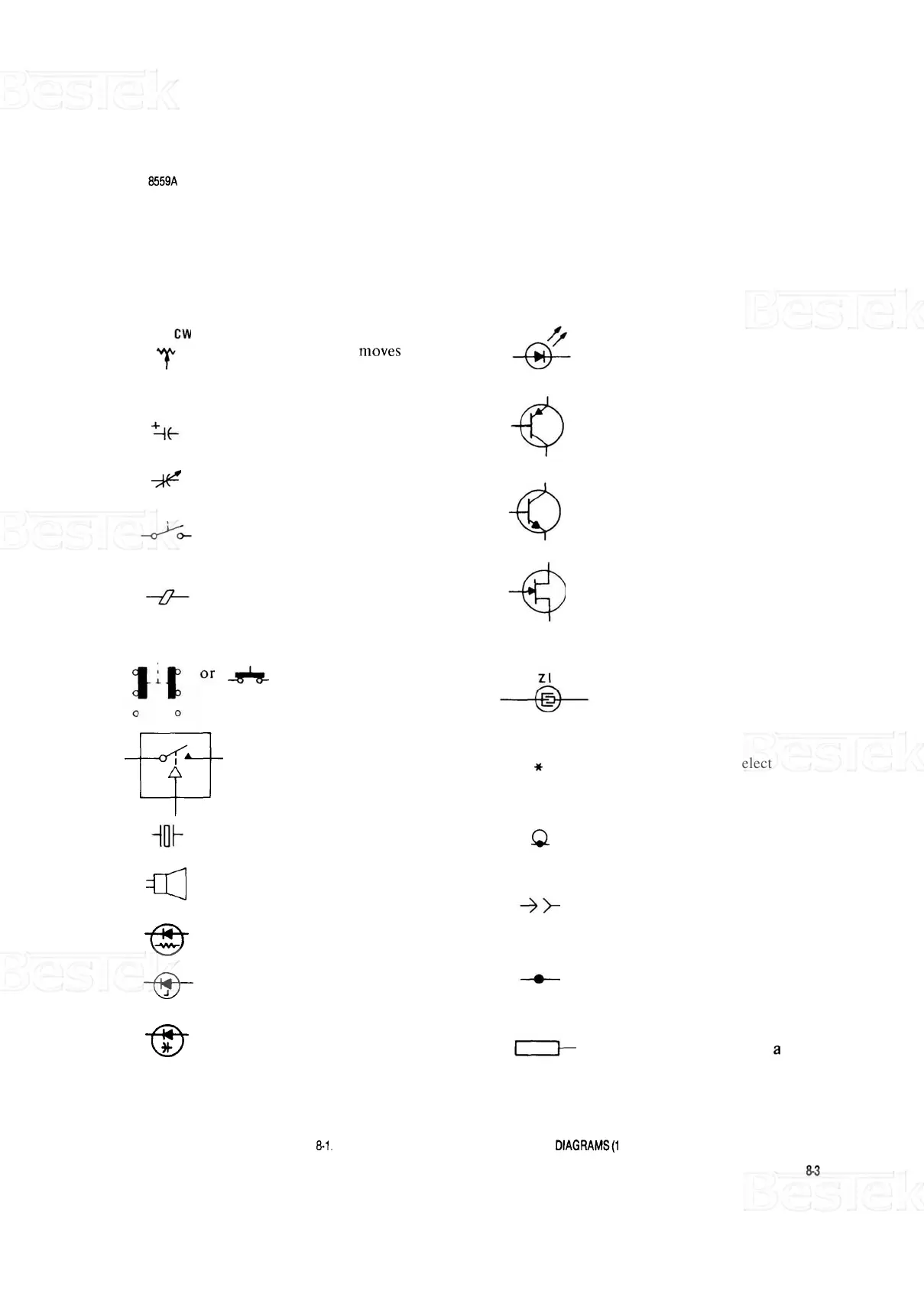
SYMBOLS USED IN SCHEMATICS AND BLOCK DIAGRAMS
BASIC COMPONENT SYMBOLS
Variable Resistor: Clockwise
rotation of shaft
moves wiper
towards end of resistor mark
-
ed CW.
Light
-
emitting diode
Transistor, PNP
Electrolytic capacitor
Variable capacitor
Transistor,
NPN
Slide, toggle, or rocker
switch
MOS
-
FET, N
-
Channel
Ferrite bead (prevents high
frequency parasitic
oscillations)
Pushbutton switch
Surface Acoustic Wave
Resonator (SAWR)
fP
Relay
Indicates a factory
-
select
component
Crystal
Indicates shielding conductor
for cables
-03
Speaker
Indicates a plug
-
in
connection
-6
Pin Diode
Indicates a soldered or
mechanical connection
6-
Breakdown (zener) diode
6-
Varactor Diode
Indicates a single pin
of
PC board edge connector
%
-
Schottky diode
FIGURE
El.
SYMBOLS USED IN SCHEMATIC AND BLOCK DIAGRAMS(1
OF4)

 Loading...


