115
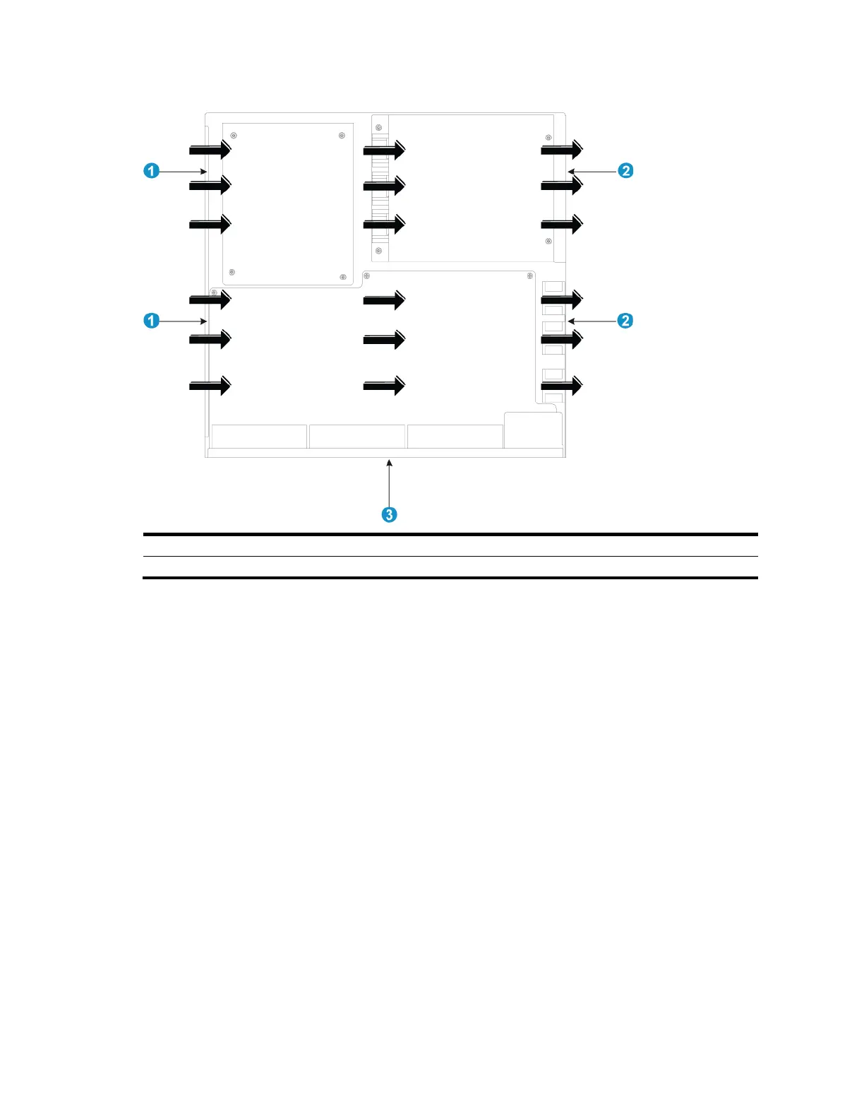
Figure 97 Airflow through the chassis
(1) Left-side inlet air vents
(2) Right-side outlet air vents
A5800AF-48G
The fan trays in the A5800AF-48G switch must be the same type: LSWM1FANSC or LSWM1FANSCB.
When LSWM1FANSC fan trays are used, cool air flows in through the air vents in the fan tray panel
and the power supply panels, circulates through the chassis and the power supplies, and exhausts at
the network port side, as shown in Figure 98.
When LSWM1FANSCB fan trays are used, cool air flows in through the air vents in the network
port-side panel and the power supply panels, circulates through the chassis and the power supplies,
and exhausts through the air vents in the fan tray panels, as shown in Figure 99.
 Loading...


