8
Table 6 Rack-mounting procedures at a glance
A5800-48G-PoE+ (2 slots)
A5800-48G-PoE+ TAA (2 slots)
A5820X-14XG-SFP+ (2 slots)
A5820X-14XG-SFP+ TAA (2 slots)
1. Identifying the mounting position
2. Attaching the mounting brackets to the chassis (for
all the switches except the A5800AF-
48G/A5820AF-24XG)
3. Rack-mounting an A5800/A5820X switch except
the A5800AF-48G/A5820AF-24XG
4. Identifying the mounting position
5. Attaching the mounting brackets, chassis rails, and
grounding cable (A5800AF-48G/A5820AF-24XG)
6. Rack-mounting an A5800AF-48G/A5820AF-24XG
switch
All other A5800 switches
A5820X-24XG-SFP+
A5820X-24XG-SFP+ TAA
7. Identifying the mounting position
8. Attaching the mounting brackets to the chassis (for
all the switches except the A5800AF-
48G/A5820AF-24XG)
9. Rack-mounting an A5800/A5820X switch except
the A5800AF-48G/A5820AF-24XG
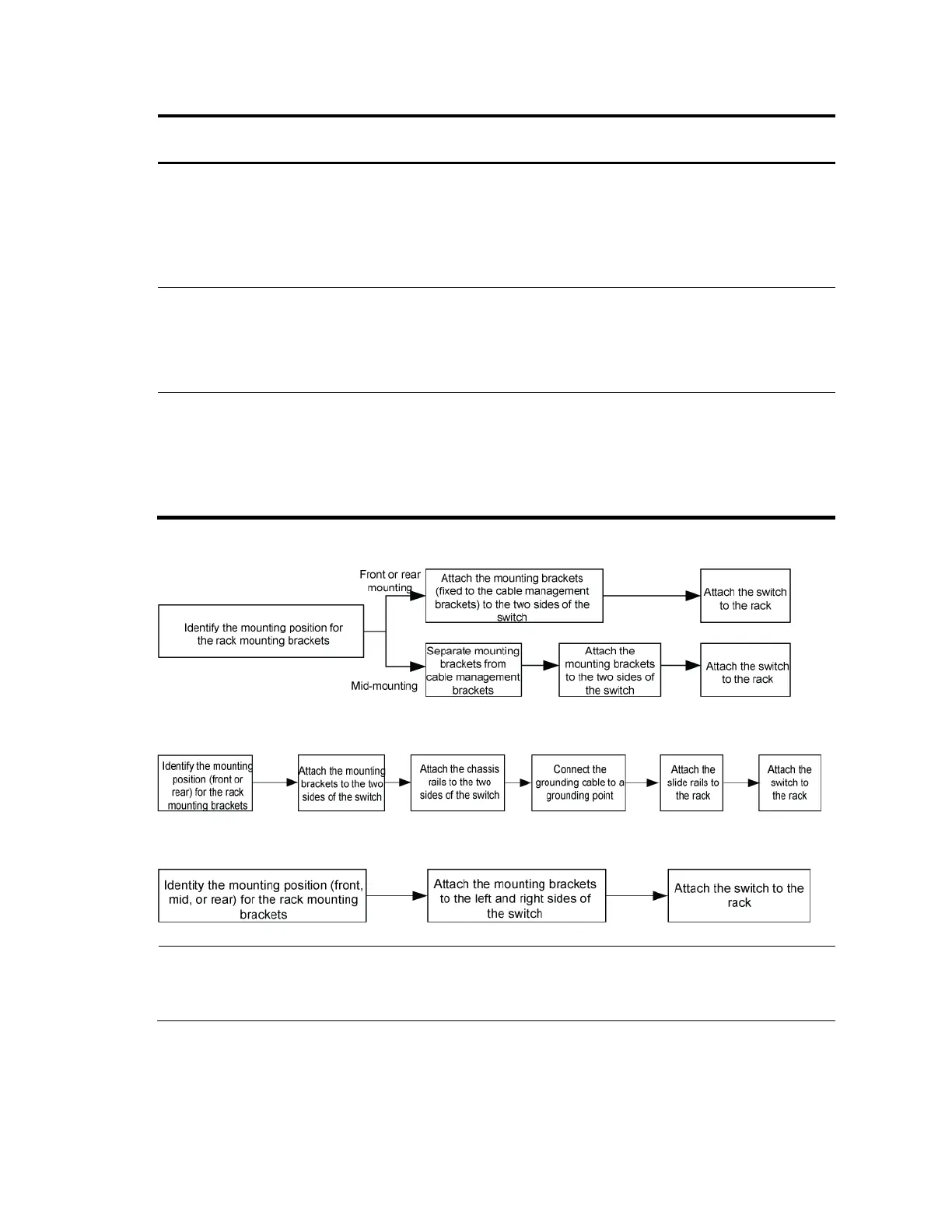
Figure 5 Rack-mounting procedure (I)
Figure 6 Rack-mounting procedure (II)
Figure 7 Rack-mounting procedure (III)
NOTE:
If a rack shelf is available, you can put the switch on the rack shelf, slide the switch to an appropriate
location, and attach the switch to the rack with mounting brackets.
Identifying the mounting position
Table 7 describes the mounting positions for the A5800AF-48G and A5820AF-24XG switches and Table
8 describes the mounting positions for all the other switches in this series.
 Loading...


