60
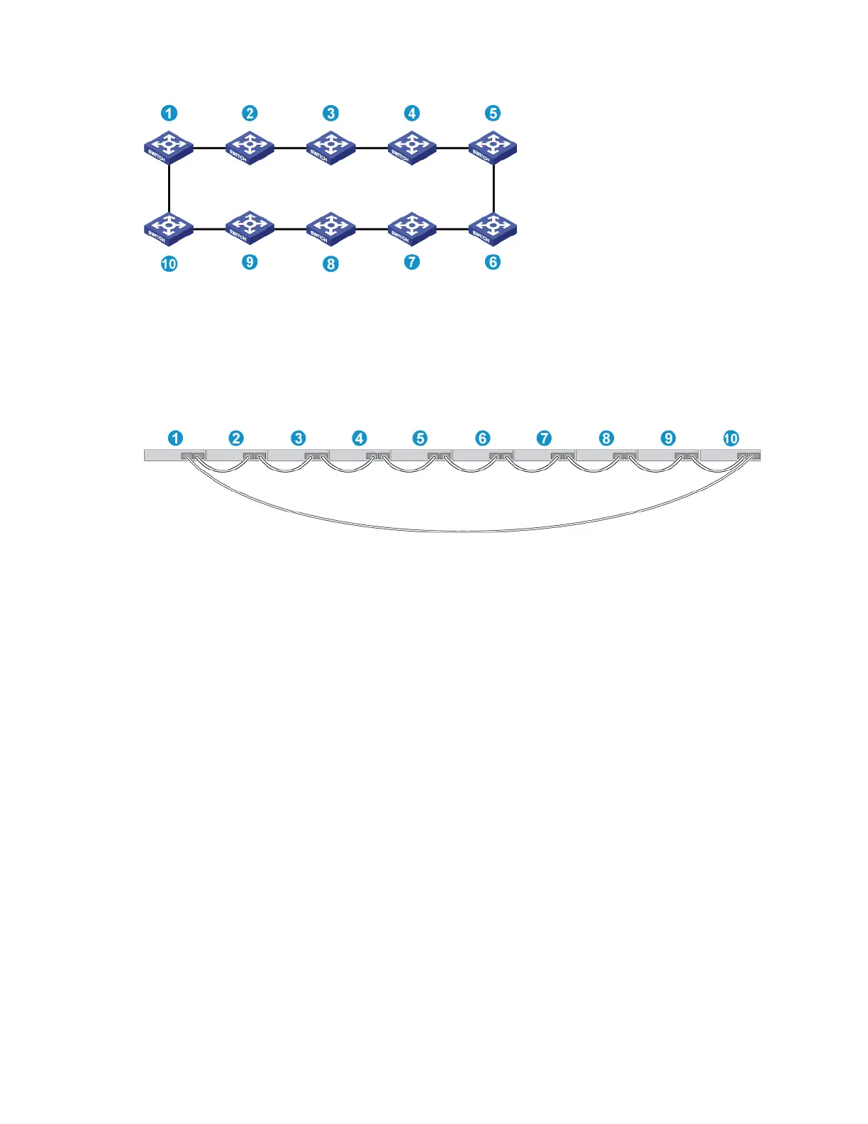
Figure 67 IRF fabric topology
Connecting the IRF member switches in a ToR solution
You can install IRF member switches in different racks side by side to deploy a ToR solution.
Figure 68 shows an example for connecting 10 top of rack IRF member switches by using SFP+
transceiver modules and optical fibers. The topology is the same as Figure 67.
Figure 68 Using both long-haul and short-haul SFP+ cables for the ring connection
Configuring basic IRF settings
After you install the IRF member switches, power on the switches, and log in to each IRF member switch
(see HP A5820X & A5800 Switch Series Fundamentals Configuration Guide) to configure their member
IDs, member priorities, and IRF port bindings.
Follow these guidelines when you configure the switches:
Assign the master switch higher member priority than any other switch.
Bind physical ports to IRF port 1 on one switch and to IRF port 2 on the other switch. You perform
IRF port binding before or after connecting IRF physical ports depending on the software release.
To bind the ports on an interface card to an IRF port, you must install the interface card first. For how
to install an interface card, see HP A5820X & A5800 Switch Series Interface Cards User Guide.
Execute the display irf configuration command to verify the basic IRF settings.
For more information about configuring basic IRF settings, see HP A5820X & A5800 Switch Series IRF
Configuration Guide.
 Loading...


