84
NOTE:
The A5800-24G-SFP (1 slot) and A5800-24G-SFP TAA (1 slot) switches come with power supply slot 1
empty and power supply slot 2 covered by a filler panel. You can install one or two power supplies for
the switch as needed. In this figure, two PSR150-A AC power supplies are installed in the slots.
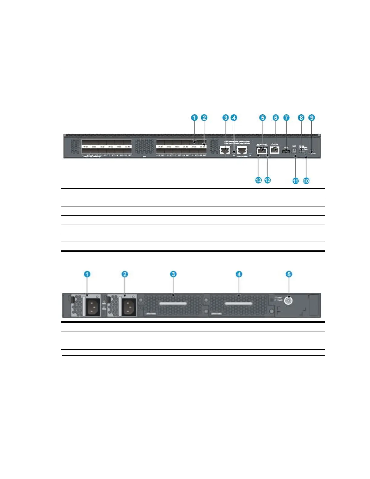
A5820AF-24XG panel views
Figure 86 Front panel
(3) 10/100/1000Base-T auto-sensing Ethernet port
(4) 10/100/1000Base-T Ethernet port LED
(5) Management Ethernet port
(8) Port LED mode switching button
(9) System status LED (SYS)
(12) ACT LED for the management Ethernet port
(13) LINK LED for the management Ethernet port
Figure 87 Rear panel
(5) Grounding screw (auxiliary grounding point 2)
NOTE:
The A5820AF-24XG switch comes with the power supply slots empty and the power filler modules as
accessories. You can install one or two power supplies for your switch as needed. In this figure, two 650W AC
power supplies are installed.
The switch also comes with the fan tray slots empty. You must install two fan trays for the A5820AF-24XG for
adequate heat dissipation, and their models must be the same. In this figure, two LSWM1FANSC fan trays are
installed.
 Loading...


