120
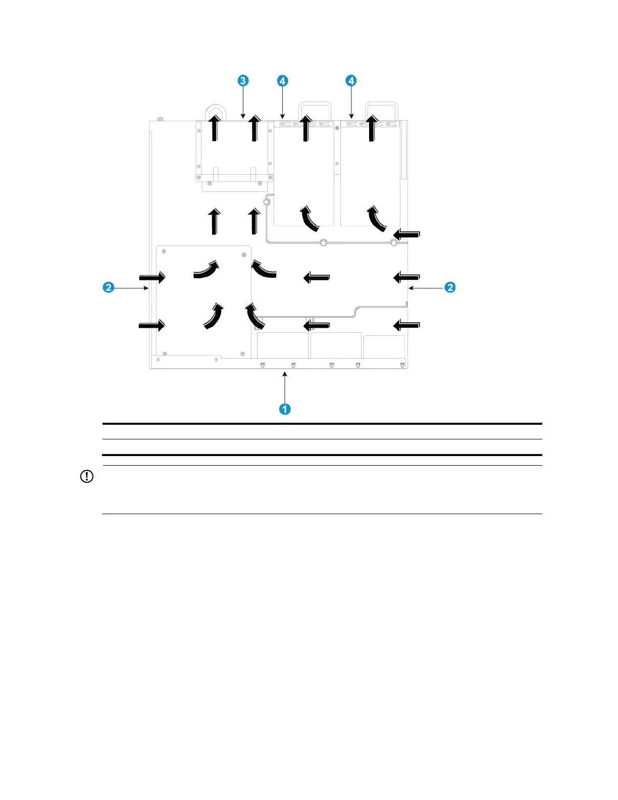
Figure 102 Airflow through the chassis
(3) Outlet air vents in the fan tray panel
(4) Outlet air vents in the power supply panels
IMPORTANT:
The chassis and the power supplies use separate air aisles. Make sure that both aisles have good
ventilation.
A5820AF-24XG
The fan trays in the A5820AF-24XG switch must be the same type: LSWM1FANSC or LSWM1FANSCB.
When LSWM1FANSC fan trays are used, cool air flows in through the air vents in the fan tray panel
and the power supply panels, circulates through the chassis and the power supplies, and exhausts at
the network port side, as shown in Figure 103.
When LSWM1FANSCB fan trays are used, cool air flows in through the air vents in the network
port-side panel and the power supply panels, circulates through the chassis and the power supplies,
and exhausts through the air vents in the fan tray panels, as shown in Figure 104.
 Loading...


