23
3. Grasp the handle of the fan tray with one hand and pull the fan tray part way out the slot. Support
the fan tray bottom with the other hand, and pull the fan tray slowly along the guide rails out of the
slot.
4. Put away the removed fan tray in an antistatic bag for future use.
Installing/removing a power supply
WARNING!
In power redundancy mode, you can replace a power supply without powering off the switch but you
must follow the installation and procedures in Figure 27 and Figure 28 closely to avoid any bodily
injury or damage to the switch.
The A5800-48G-PoE+ (2 slots), A5800-48G-PoE+ TAA (2 slots), A5800-24G-SFP (1 slot), and A5800-
24G-SFP TAA (1 slot) switches, and all the A5820X switches except the A5820AF-24XG come with power
supply slot 1 empty and power supply slot 2 covered by a filler panel. The A5800AF-48G and
A5820AF-24XG switches come with both power supply slots empty and the power filler modules as
accessories.
You can install one or two power supplies for these switches as needed. For more information about the
power supplies available for the switches, see ―Hot swappable power supplies.‖
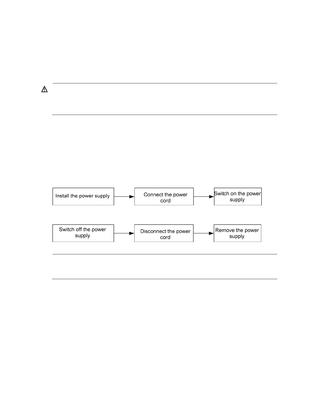
Figure 27 Installation procedure
Figure 28 Removal procedure
NOTE:
The HP A58x0AF 650W AC power supply and the HP A58x0AF 650W DC power supply are referred
to as the 650W AC power supply and the 650W DC power supply throughout this installation guide.
A5800AF-48G/A5820AF-24XG
Installing a power supply
To install a 650W AC power supply or 650W DC power supply into an A5800AF-48G or A5820AF-
24XG switch:
1. Wear an ESD-preventive wrist strap and make sure it makes good skin contact and is well
grounded.
2. Unpack the power supply and check that the power supply model is correct. If only one power
supply is installed, install a power filler module in the empty power supply slot for good ventilation
of the switch.
 Loading...


