56
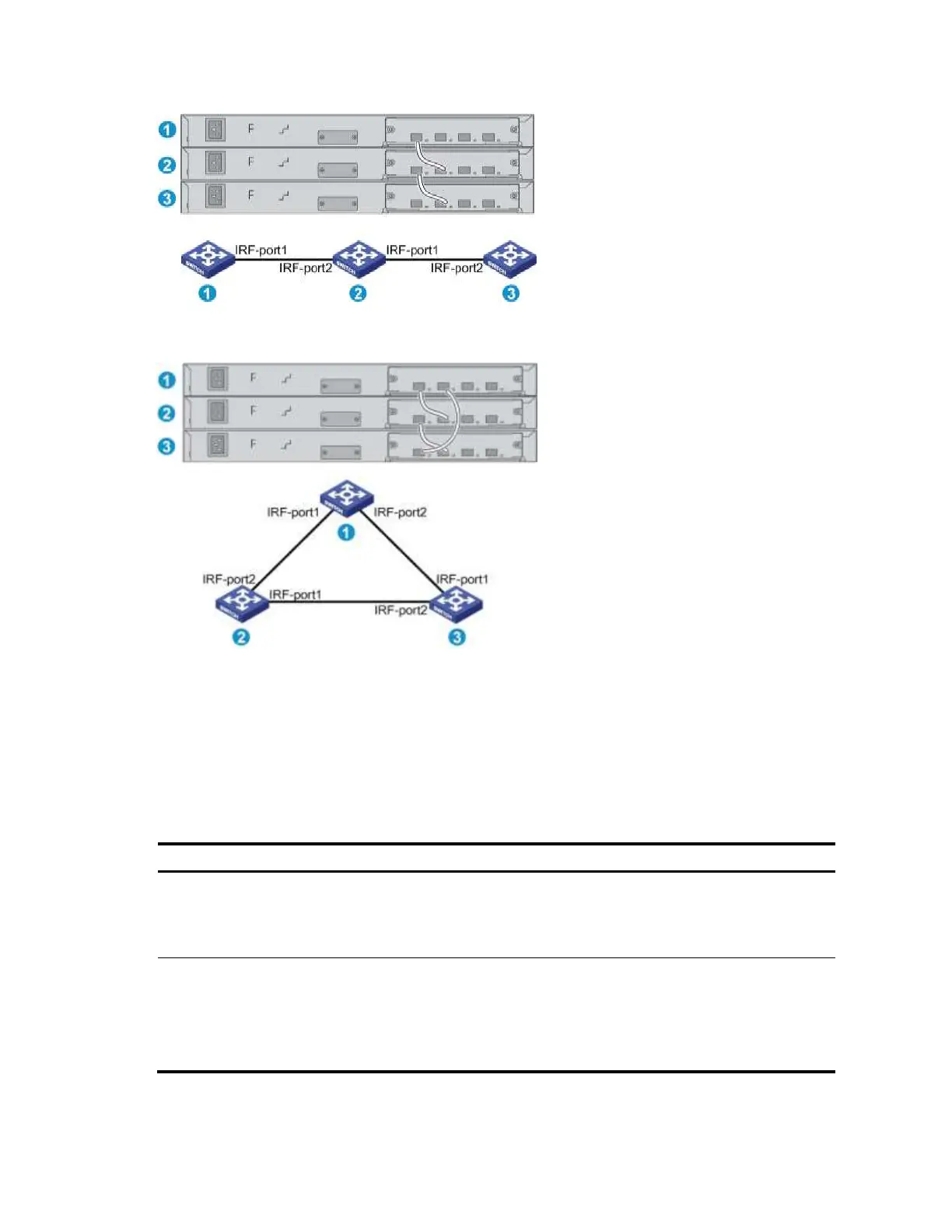
Figure 64 IRF fabric in daisy chain topology
Figure 65 IRF fabric in ring topology
Identifying physical IRF ports on the member switches
Identify the physical IRF ports on the member switches according to your topology and connection
scheme.
Table 11 shows the physical ports that can be used for IRF connection and the port use restrictions.
Table 11 Physical IRF port requirements
Candidate physical IRF ports
A5800-48G-PoE+ (2
slots)
A5800-48G-PoE+ TAA (2
slots)
Ports on the expansion interface
cards on the front panel
All physical ports of an IRF port must
be located on the same interface card.
A5800-48G (1 slot)
A5800-48G TAA (1 slot)
A5800-48G-PoE+ (1 slot)
A5800-48G-PoE+ TAA (1
slot)
The four fixed SFP+ ports on
the front panel
Ports on the expansion
interface card on the rear
panel
All physical ports of an IRF port must
be located on the front panel or the
interface card on the rear panel.
 Loading...


