12
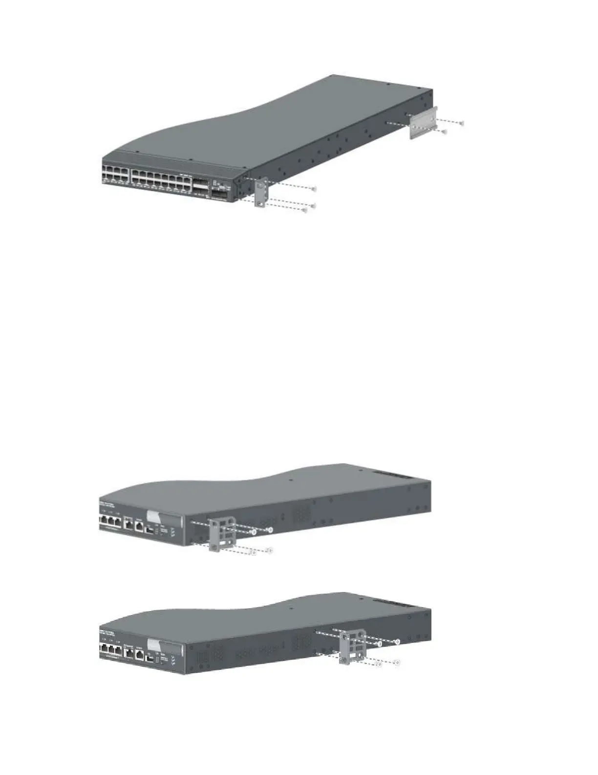
Figure 10 Attaching the front mounting brackets and the chassis rails to the chassis
Attaching the mounting brackets to the chassis (for all the
switches except the A5800AF-48G/A5820AF-24XG)
All A5800 and A5820X switches except the A5800AF-48G and the A5820AF-24XG have three
mounting positions: one front mounting position (near the network ports), one mid-mounting position, and
one rear mounting position (near the power supplies).
To attach the mounting brackets in one of these positions:
1. Align one mounting bracket with the screw holes in the front-mounting position (Figure 11), mid-
mounting position (Figure 12), or the rear-mounting position (Figure 13).
These figures show attaching a 1U bracket to a 1U switch chassis. To attach a 2U bracket to a 2U
switch chassis, see Figure 14.
2. Use M4 screws (supplied with the switch) to attach the mounting bracket to the chassis.
3. Repeat the proceeding steps to attach the other mounting bracket to the chassis.
Figure 11 1U mounting bracket front mounting position
Figure 12 1U
bracket mid-mounting
position
 Loading...


