Procedure
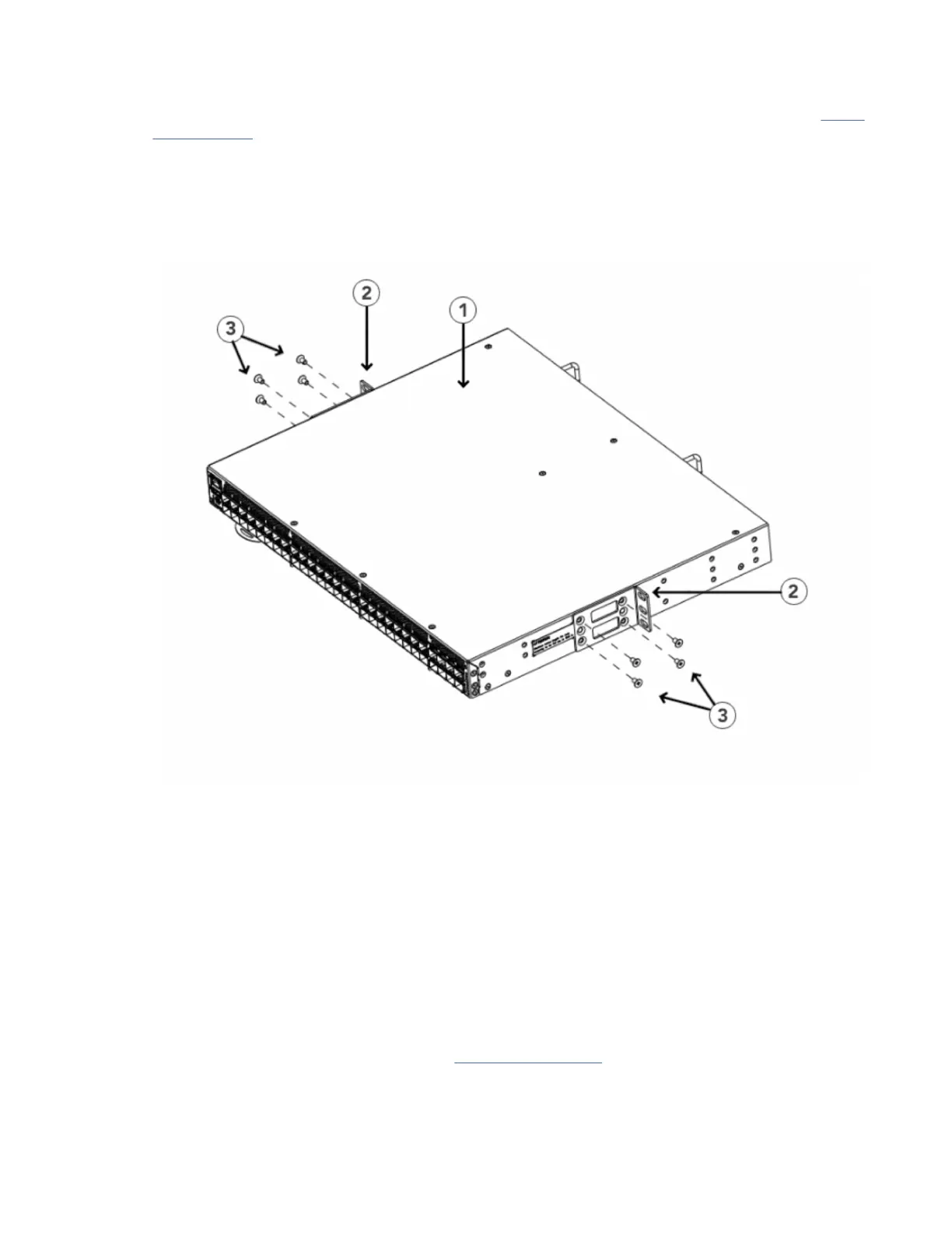
1. Position the right front bracket with the flat side against the right side of the device, as shown in Figure
21 on page 32.
2. Insert four 8-32 x 5/16-in. flathead screws through the vertically aligned holes in the bracket and then
into the holes on the side of the device. Use the upper and lower screw holes, leaving the center holes
empty.
3. Repeat step 1 and step 2 to attach the left front bracket to the left side of the device.
4. Tighten all the 8-32 x 5/16-in. screws to a torque of 15 in-lb (17 cm-kg).
Figure 21. Attaching the front brackets
1 - The SAN64B-6 switch
2 - Front brackets, right and left
3 - Screws, 8-32 x 5/16-in., flathead Phillips
Attaching the front brackets to the rack
About this task
Complete the following steps to install the device in the rack.
Procedure
1. Position the device in the rack, as shown in Figure 22 on page 33, providing temporary support under
the device until the rack kit is fully secured to the rack.
2. Attach the right front bracket to the right rack upright using two 10-32 x 5/8-in. screws and two
retainer nuts. Use the upper and lower holes in the bracket.
32
IBM Storage Networking SAN64B-6: SAN64B-6 Installation, Service, and User Guide
 Loading...