• Leave at least 1 m (3.28 ft) of slack for each port cable. This provides room to remove and replace the
switch, allows for inadvertent movement of the rack, and helps prevent the cables from being bent to
less than the minimum bend radius.
• If you are using IBM ISL Trunking, consider grouping cables by trunking groups. The cables used in
trunking groups must meet specic requirements, as described in the Fabric OS Administrator’s Guide.
• For easier maintenance, label the ber-optic cables and record the devices to which they are
connected.
• Keep LEDs visible by routing port cables and other cables away from the LEDs.
• Use hook and loop style straps to secure and organize ber-optic cables.
Installing an SFP+ transceiver
About this task
The device supports only IBM-qualied transceivers. If you use an unqualied transceiver, the
switchshow command output shows the port in a Mod_Inv state. Fabric OS also logs the issue in the
system error log. To insert an SFP+ transceiver, complete the following steps:
Note: The 16- and 32-Gbps SFP+ transceivers do not have bails. Always use the pull tab to insert or
remove the transceivers, as the SFP might be hot.
Procedure
1. Use the pull tab on the 16- and 32-Gbps SFP+ transceivers to help push the transceiver into the port.
Transceivers are keyed so that they can only be inserted with the correct orientation. If a transceiver
does not slide in easily, ensure that it is correctly oriented. Push the correctly oriented transceiver into
the port until it is rmly seated and the latching mechanism clicks.
Note: Each SFP+ transceiver has a 10-pad gold-plated PCB-edge connector on the bottom. The
correct position to insert an SFP+ transceiver into the upper row of ports is with the gold edge down.
The correct position to insert an SFP+ transceiver into the lower row of ports is with the gold edge up.
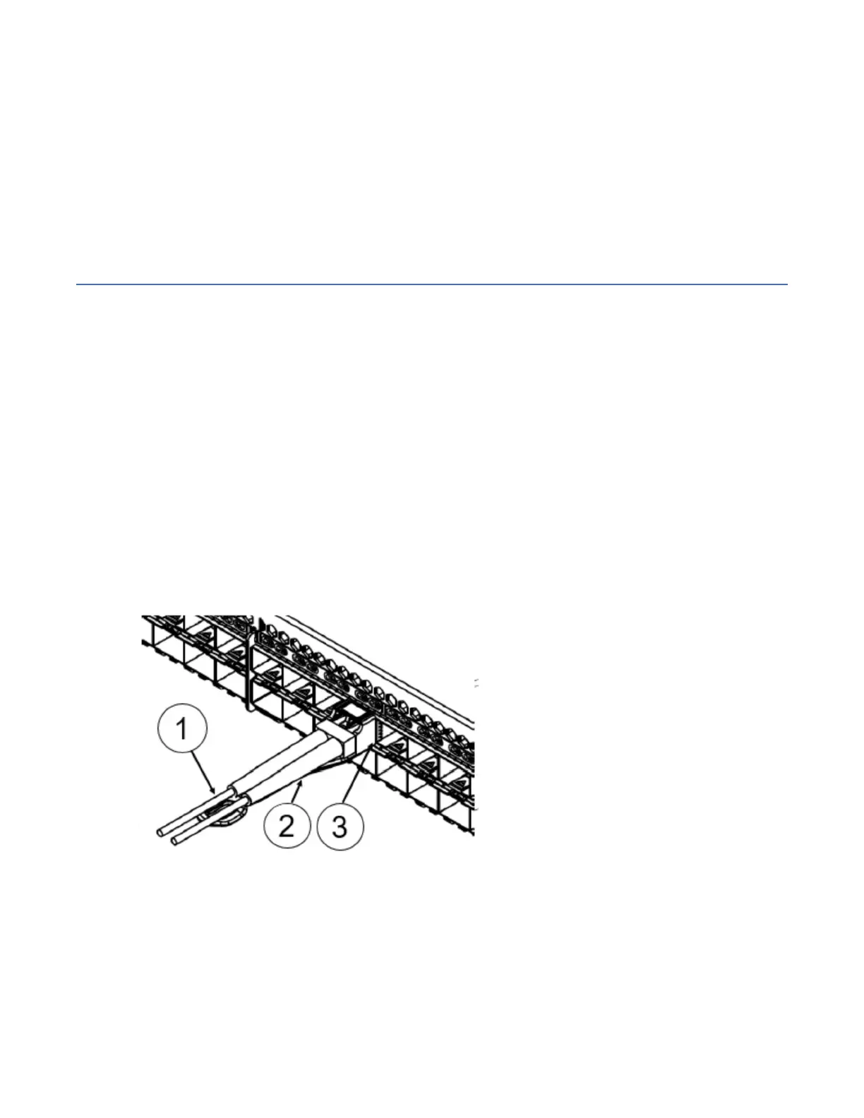
Figure 26. Installing a 32-Gbps SFP+ transceiver into an upper port
1 - Pull tab
2 - SFP Cable
3 - SFP Transceiver
2. Position a cable so that the key (the ridge on one side of the cable connector) is aligned with the slot in
the transceiver. Insert the cable into the transceiver until the latching mechanism clicks.
Note: Cables are keyed so that they can be inserted in only one way. If a cable does not slide in easily,
ensure that it is correctly oriented. Do not insert any unsupported cable intended for an other type of
transceiver into a regular SFP+ transceiver. You may damage the cable as well as the transceiver.
Chapter 5. Installing transceivers and cables
49
 Loading...