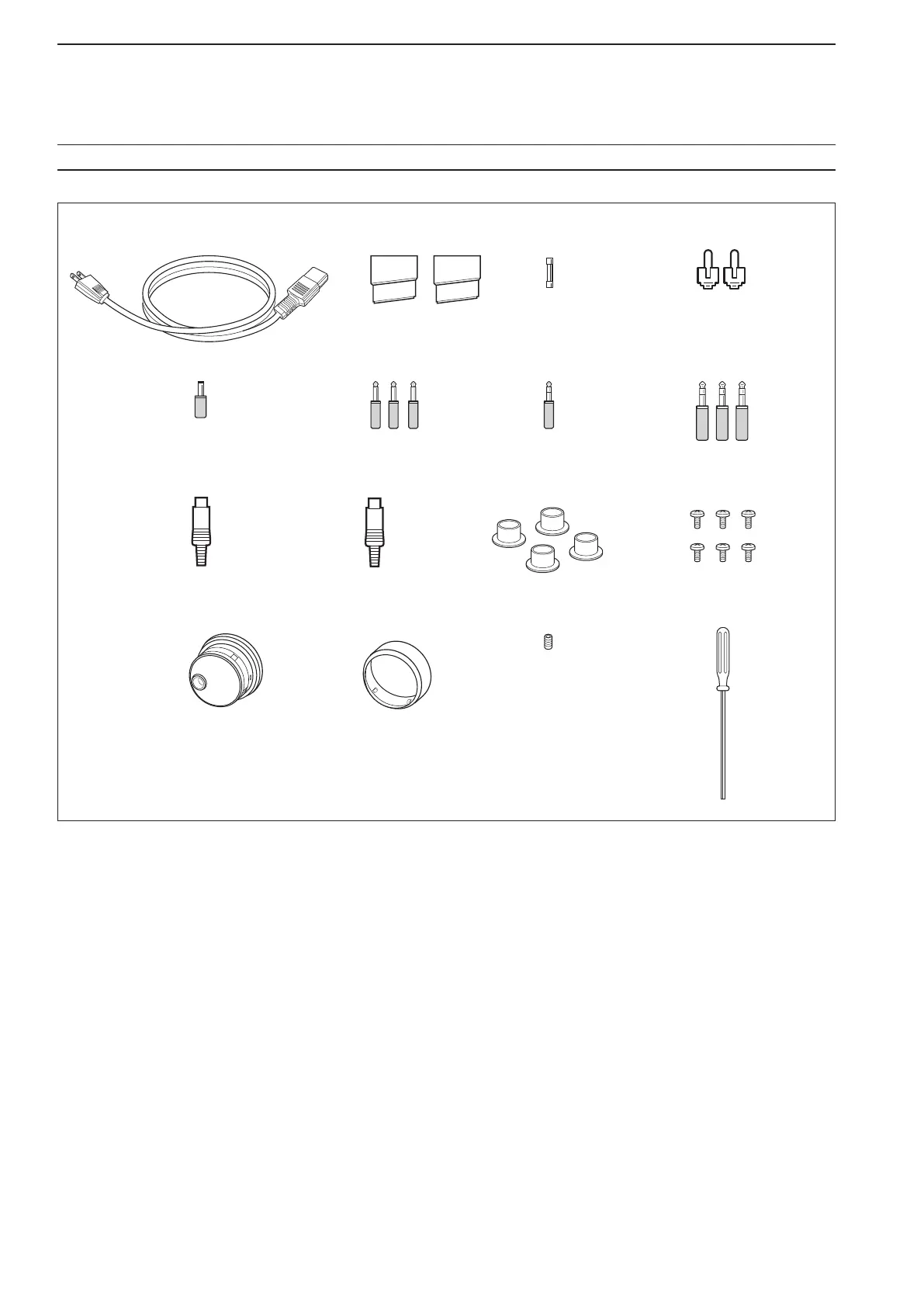
q AC power cable* ................................................. 1
w Feet .............................................................. 1 pair
e Spare fuse (FGB 2 A) ......................................... 1
r RCA plugs ........................................................... 2
t DC plug ............................................................... 1
y 2-conductor
1
⁄8″ plugs ......................................... 3
u 3-conductor
1
⁄8″ plugs ......................................... 2
i 3-conductor
1
⁄4″ plugs ......................................... 3
o ACC plugs (7-pin) ............................................... 1
!0 ACC plugs (8-pin) ............................................... 1
!1 Antenna connector caps ..................................... 4
!2 Side screws (without rack mounting handle)
†
..... 6
!3 Main dial
‡
............................................................. 1
!4 Rubber cover for the Main dial
‡
............................ 1
!5 Main dial screw
‡
................................................... 1
!6Hexagonalwrench
‡
.............................................. 1
*
May differ from that shown depending on the version.
†
These screws are used when removing the rack mounting
handles. See p.2-3 for the rack mounting handle detach-
ment details.
‡
See p.2-2 for the main dial attachment details.
iii
SUPPLIED ACCESSORIES
q
!0 !1 !2
!3 !4 !5 !56
yui
o
ewr
t
!2
!3
(FH M4×12 mm)
(PH M4×8 mm)
PH: Pan head
FH: Flat head

 Loading...


