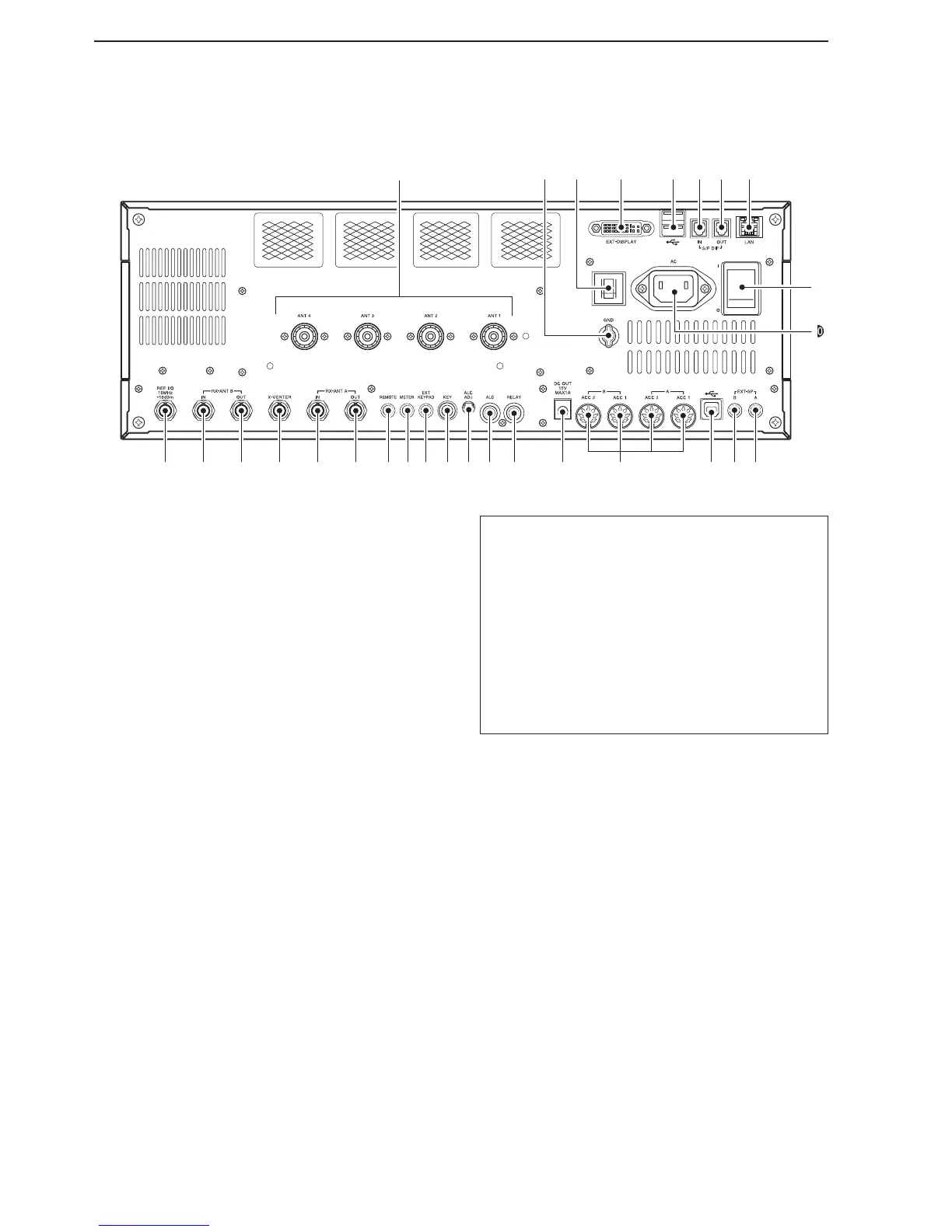
q ANTENNA CONNECTOR [ANT 1–4] (p. 3-4)
Connects to a 50 Ω antenna with a PL-259 plug
connector.
w GROUND TERMINAL [GND] (p. 3-2)
Connect this terminal to ground to prevent electrical
shocks, TVI, BCI and other problems.
e CIRCUIT BREAKER
Cuts off the AC input if excessive current flows.
r EXTERNAL DISPLAY TERMINAL [EXT-DISPLAY]
(p. 3-6)
Connects to an external display monitor.
• At least 800×600 pixel display is necessary.
t USB (Universal Serial Bus) PORT [USB A]
Insert a USB flash drive* for both reading and
storing a wide variety of the transceiver’s infor-
mation and data.
• The indicator lights or blinks when the transceiver
reads or writes to the memory data.
• An unmount operation should be performed before
removing the USB flash drive*.
Connects to a PC keyboard for RTTY and PSK
operations.
• USB keyboards* are supported.
*: A USB flash drive or USB keyboard is not supplied
by Icom.
About the [USB A] connector:
• Supports only a USB ash drive, keyboard, mouse
or hub.
• Turn the transceiver power OFF when connecting
or disconnecting a USB keyboard, mouse or hub.
• DO NOT connect the following devices:
- Two or more of the same kind of USB devices.
(Example: Two USB hubs or two USB mice)
- A Multimedia adapter
- A USB HDD
- A USB flash drive larger than 32 GB
- A Bluetooth
®
keyboard or mouse.
y S/P DIF INPUT TERMINAL [S/P DIF– IN]
u S/P DIF OUTPUT TERMINAL [S/P DIF– OUT]
Connects to external equipment that supports S/P
DIF input/output.
i ETHERNET CONNECTOR [LAN] (p. 3-6)
Connects to a PC network through a LAN (Local
Area Network).
o MAIN POWER KEY [I/O] (p. 4-3)
Turns the internal power supply ON or OFF.
!0 AC POWER SOCKET [AC] (p. 3-4)
Connects the supplied AC power cable to an AC re-
ceptacle.
!1
EXTERNAL SPEAKER JACK MAIN [EXT-SP A]
(p. 3-5)
!2
EXTERNAL SPEAKER JACK SUB [EXT-SP B]
(p. 3-5)
Connects to an external speaker (4–8 Ω), if de-
sired.

 Loading...