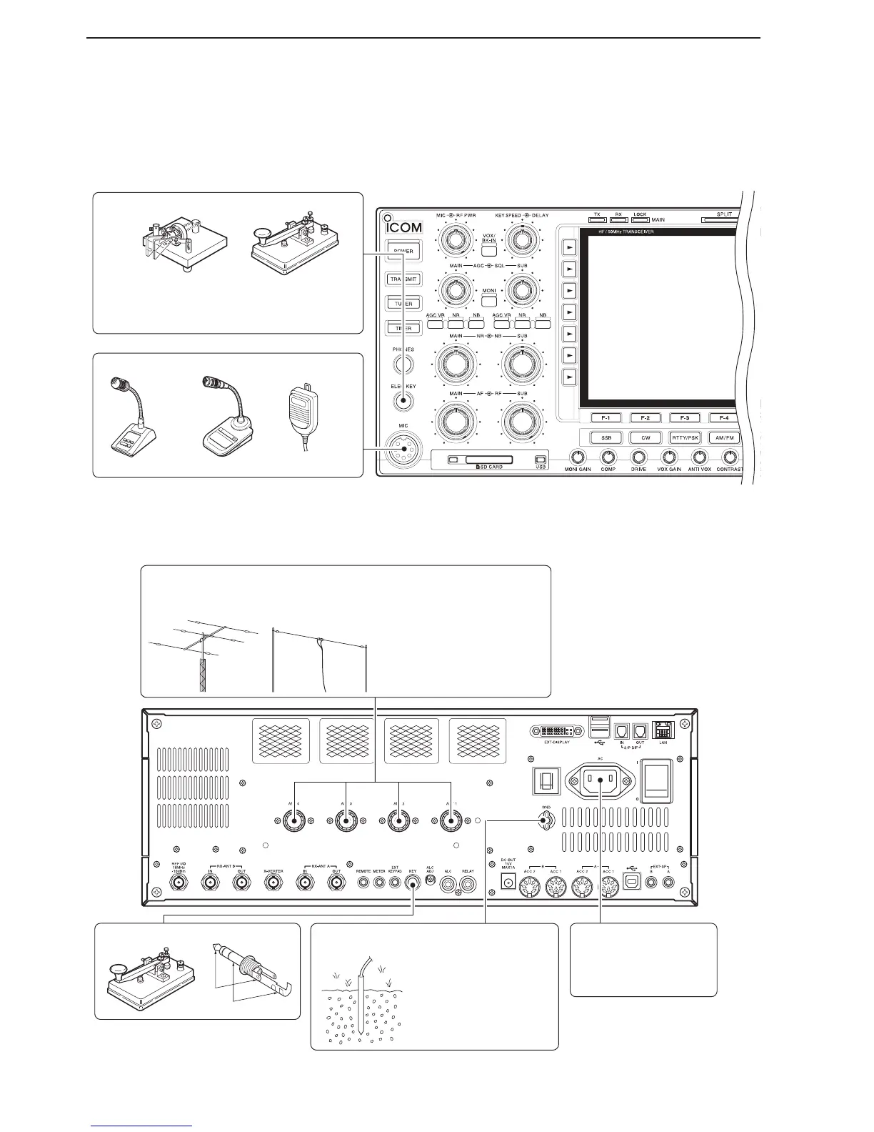
Microphones (pp. 3-9, 3-10)
CW key
A straight or bug key can be used when the
internal electronic keyer is turned OFF in
keyer set mode. (p. 5-13)
Optional
HM-36
Optional
SM-50
Optional
SM-30
L
B
Straight key
Antenna 1, 2, 3, 4 (p. 13-2)
Ground
(p. 3-2)
Use the heaviest gauge
wire or strap available and
make the connection as
short as possible.
Grounding prevents
electrical shock, TVI and
other problems.
AC outlet
R WARNING!
Use only the supplied
AC power cable.
NOTE: Attach the sup-
plied antenna connec-
tor cap when no anten-
na or external equip-
ment is connected.
[Example]: ANT1 for the 1.8–18 MHz bands, ANT 2 for the 21–28 bands
ANT3 for the 50 MHz band, and ANT 4 for a receive antenna.
+
_

 Loading...