EasyManua.ls Logo

Inovance Monarch 220-NICE-L-C-4022F User Manual

Inovance Monarch 220-NICE-L-C-4022F
368 pages
To Next Page IconTo Next Page
To Previous Page IconTo Previous Page
Page #121 background imageLoading...
Page #121 background image
3 Peripheral Devices and Options
-
120
-
3.3.4 Car Call Board (MCTC-CCB)
The car call board (MCTC-CCB) is another interface between users and the control sys-
󶍿
buttons and 8 functional signals. The CCB mainly collects button calls and outputs
󶍿
through cascaded connection. CN2 is an input connector and CN1 is a cascaded out-
put connector.
1 Appearance and dimensions
1 2 3 4
1 2 3 4
1 2 3 4
1 2 3 4
1 2 3 4
1 2 3 4
1
2 3 4
1
2 3 4
1 2 3 4
1 2 3 4
1
2
3 4
1 2 3 4
1
2 3 4
1 2 3 4
1 2 3 4
1 2
3 4
1 2 3 4
1 2 3 4
1 2 3 4
1 2 3 4
1
2 3 4
1 2 3 4
1 2 3 4
1 2 3 4
JP1 JP2 JP3
JP4
JP5 JP6 JP7 JP8
JP9 JP10 JP11 JP12
JP13 JP14 JP15 JP16
JP17 JP18 JP19 JP20
JP21 JP22 JP23 JP24
CN1
Buzzer
Floor 1 Floor 2 Floor 3 Floor 4
Floor 5 Floor 6 Floor 7 Floor 8
Floor 9 Floor 10 Floor 11 Floor 12
Floor 13 Floor 14 Floor 15 Floor 16
Attend
ant
Direction
Change
Independent
running
Fire
emergen
cy
Door
open
Door
close
Door open
delay
Direct
travel
ride
MCTC-CCB
CN2
R2.5
158
148
69
79
2
1
MCTC-CCB
1 - Plastic support higher than
1 cm
2 - Self-
tapping screw 4-φ4.
9x30
󶙽Appearance, structure and installation method of the CCB

Table of Contents

Other manuals for Inovance Monarch 220-NICE-L-C-4022F

Question and Answer IconNeed help?

Do you have a question about the Inovance Monarch 220-NICE-L-C-4022F and is the answer not in the manual?

Inovance Monarch 220-NICE-L-C-4022F Specifications

General IconGeneral
Product nameInovance Monarch 220-NICE-L-C-4022F
Model220-NICE-L-C-4022F
Rated voltage220V
Control modeVector control
ApplicationIndustrial automation
Output Current2.2 A
Control MethodV/F control, Sensorless vector control
Communication InterfaceModbus RTU
Protection FeaturesOvercurrent, Overvoltage, Overheat, Short circuit
Humidity5% to 95% (non-condensing)

Summary

Preface

1 More advanced technology

Details the advanced technological features of the NICE3000new controller, including drive ride and communication.

3 Safer running

Focuses on safety features, fault tolerance, and environmental adaptability for secure operation.

Introduction

1 Basic functions

Details fundamental functionalities like collective selective operation, service floor settings, and door control.

1 Product Information

1.1 Designation Rule and Nameplate

Explains the model designation rules and details found on the controller's nameplate.

1.2 Description of components

Provides an overview of the physical components of the controller, illustrating their locations.

1.5 System Configuration

Illustrates the system components and their interconnections for the NICE3000new control system.

2 Installation and Wiring

2.1 Installation

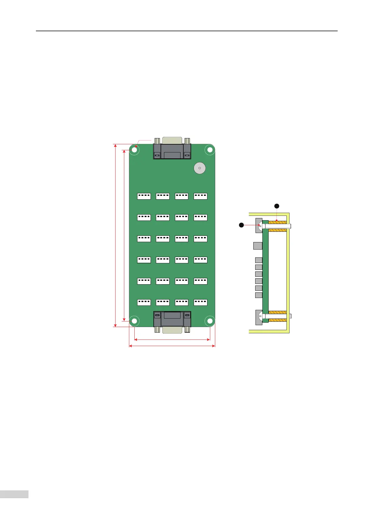
Covers installation requirements, including environment, clearance, orientation, dimensions, and procedures.

2.2 Wiring

Describes the description and wiring of main circuit and control circuit terminals, including cable sizes.

2.5 Standard Wiring of the System

Provides wiring diagrams and inspection checklists for the entire system setup.

3 Peripheral Devices and Options

3.2 Peripheral Device Selection Guide

Offers guidance on selecting cables, circuit breakers, contactors, reactors, and filters.

4 Commissioning Tools

5 System Commissioning

5.1 System Commissioning Guide

Provides a general guide to the commissioning process for the elevator system.

5.2 Safety and Circuit Check

Details crucial safety precautions and checks required before performing system commissioning.

5.3 Power-on and Controller State Check

Covers procedures for checking power-on status and handling potential controller states and faults.

5.4 Commissioning at Inspection Speed

Explains the process of motor auto-tuning and running tests at inspection speed.

5.5 Commissioning at Normal Speed

Outlines steps for commissioning at normal speed, including shaft auto-tuning and HCB setup.

6 Parameter Description

7 Troubleshooting

7.1 Elevator Fault Display

Explains how fault codes and subcodes are displayed on the keypad and operation panel.

7.4 Fault Information and Troubleshooting

Provides a table linking fault codes to possible causes and recommended solutions for troubleshooting.

9 Description of Functions and Schemes

9.13 Automatic Emergency Evacuation Scheme at Power Failure

Details how the system provides emergency evacuation during power failures using UPS or ARD.

Related product manuals