9 Description of Functions and Schemes
-
336
-
9.16 STO Application Scheme
1 Background
elevator contactor and makes the safety level reach SIL3. At stop due to faults, the
system disconnects the safety circuit and triggers the STO function; the controller
stops torque output and implements safe braking on the motor to ensure elevator
running safety.
2 Overview
The controller with the STO function and a STO card are required, as described in the
following table.
Materials Materials Model Materials Description
Special controller Customized Special NICE3000
new
controller with the STO function
STO card MCTC-JCB-A2 STO card used together with the drive board
new
and the STO
card.
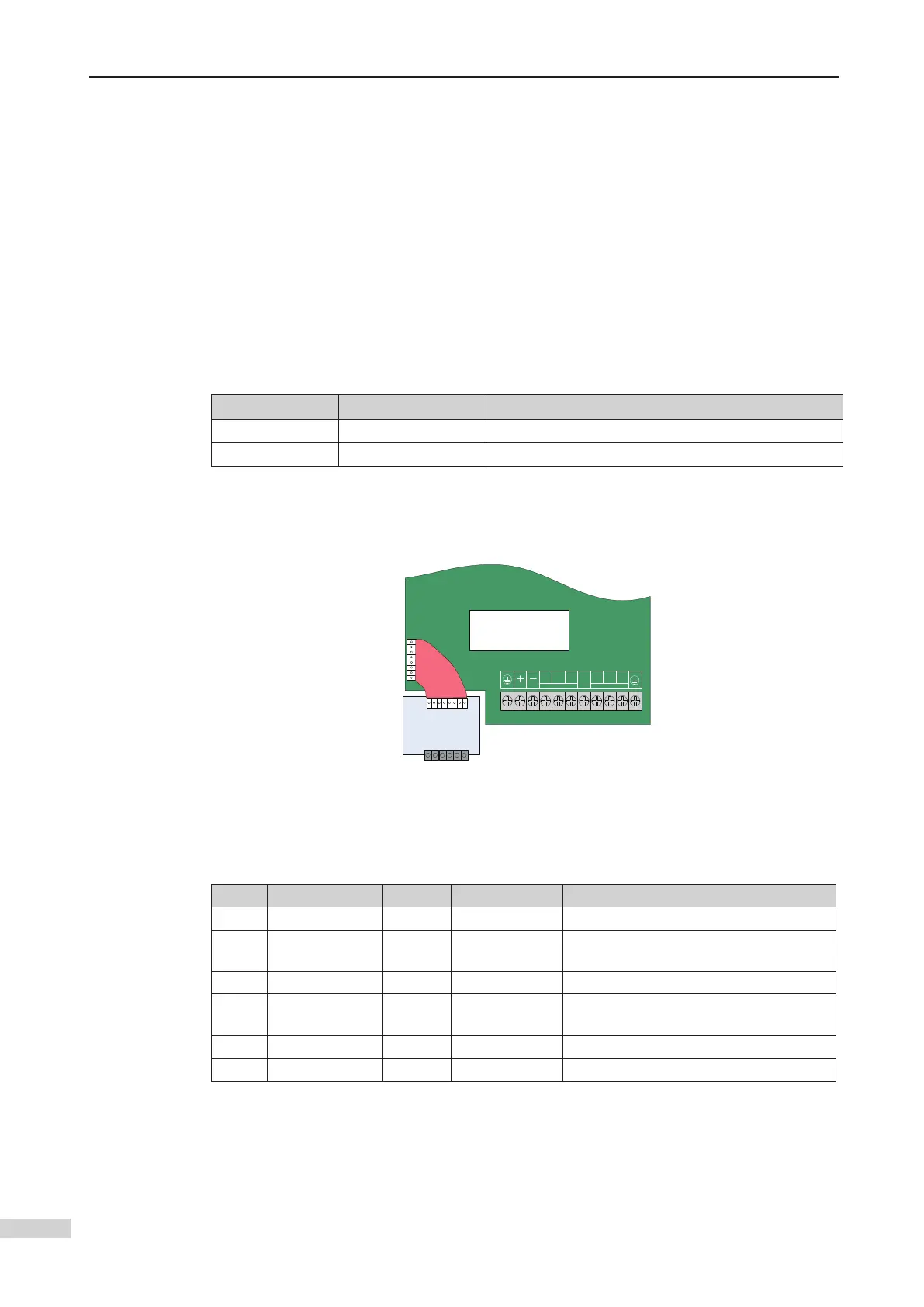
STO card
24V1
COM1
24V2
COM2
DNS+
DNS-
NICE3000
new
drive board
R
S
T
PB
U
V
W
POWER MOTOR
Connection between the controller drive board and the STO card
The description of each STO terminal is as follows:
Pin Signal Label Voltage Description
1 STOA 24V1 0 V / 24 V STO channel A input
2 GND_STOA COM1 0 V Reference ground of STO channel A
input
3 STOB 24V2 0 V / 24 V STO channel B input
4 GND_STOB COM2 0 V Reference ground of STO channel B
input
5 DNS+ DNS+ 0 V / 24 V STO feedback positive
6 DNS- DNS- 0 V STO feedback negative
STOA and STOB are the two channels of STO. Each channel can stop the output of the
AC drive. The dual-channel design is SIL3 compliant.
DNS+ and DNS- are feedback terminals of STO. They are connected to the monitor
controller to detect damage on the STO circuit.
 Loading...