9 Description of Functions and Schemes
-
322
-
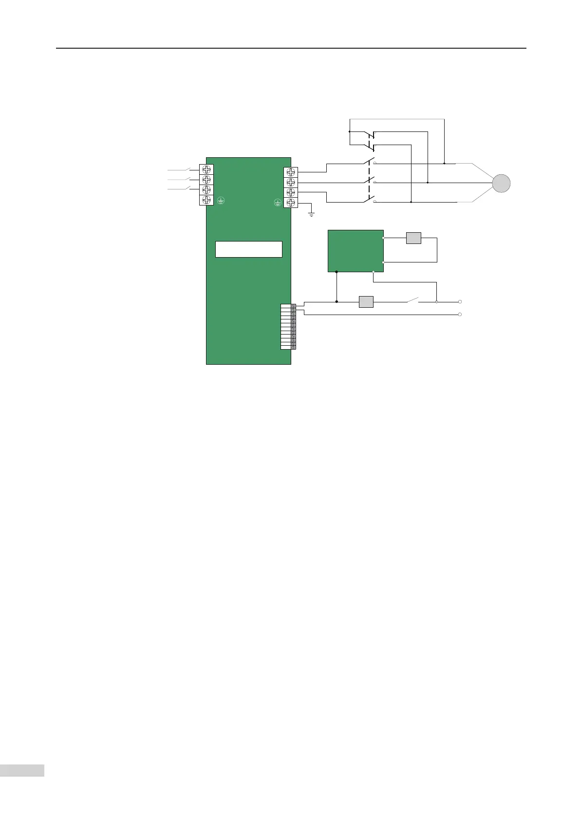
9.12.2 Scheme 2
1 Wiring
Y1
M1
FX: shorting motor stator contactor SW: RUN contactor
CN7
Y1
M1
Y2
M2
Y3
M3
Y4
M4
Y5
M5
Y6
M6
R
S
T
External
power
supply
U
V
W
5 6
FX
1
2
3
4
5 6
1
2
3
4
M
Motor
SW
SW
102
132
Shorting
delay
board
FX
A1 A2
A2- A1+
AC1
AC2
DC3
DC4
+
-
DC110
AC110
NICE3000
new
Wiring diagram of shorting delay board
2 Parameters
No parameter is needed. During running output, the AC110 and DC110 on the delay
board is live. Then, the FX shorting contactor is closed and auxiliary contact 5.6 is
actuated, and in turn, the SW run contactor is closed. The elevator starts to run.
When the elevator stops, the SW run contactor is opened, and the FX contactor is
achieved.
 Loading...